Optical structure, display device and working method thereof

An optical structure and display device technology, applied in optics, nonlinear optics, static indicators, etc., can solve problems such as the inability to switch between anti-peep display and shared display, and achieve anti-peep display, shared display, and switching Effect

Active Publication Date: 2017-05-10
BOE TECH GRP CO LTD
View PDF6 Cites 13 Cited by
  • Summary
  • Abstract
  • Description
  • Claims
  • Application Information

AI Technical Summary

Problems solved by technology

[0003] The existing anti-peeping display technology is realized by adding a special anti-peeping film on the display panel, which can only realize anti-peeping display, but cannot switch between anti-peeping display and shared display

Method used


Image

  • Optical structure, display device and working method thereof
  • Optical structure, display device and working method thereof
  • Optical structure, display device and working method thereof

Examples


Embodiment 1

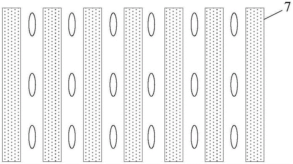
[0042] This embodiment provides an optical structure, such as figure 1 As shown, this embodiment includes:

[0043] The first electrode 5 and the second electrode 9 arranged oppositely;

[0044] a first alignment layer 6 located on the side of the first electrode 5 facing the second electrode 9;

[0045] a second alignment layer 8 located on the side of the second electrode 9 facing the first electrode 5;

[0046] Liquid crystal molecules located between the first alignment layer 6 and the second alignment layer 8;

[0047] A plurality of insulating protrusions 7 located on the side of the first alignment layer 6 facing the second alignment layer 8, the plurality of protrusions 7 are arranged at intervals and parallel to each other, and the refractive index of the protrusions 7 is the same as that of the The refractive index of the above-mentioned liquid crystal molecules is the same under the electrified state or the unenergized state;

[0048] By controlling the electric...

Embodiment 2

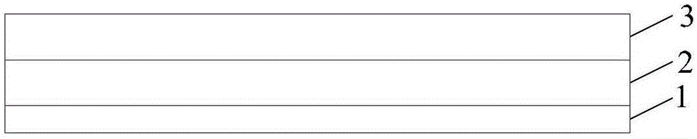
[0068] The embodiment of the present invention also provides a display device, such as image 3 shown, including:

[0069] Backlight 1;

[0070] display panel 3;

[0071] The above-mentioned optical structure 2 is located between the display panel 3 and the backlight 1 .

[0072] The display device can be any product or component with display function such as LCD TV, liquid crystal display, digital photo frame, mobile phone, tablet computer, etc., wherein the display device also includes a flexible circuit board, a printed circuit board and a backplane.

[0073] In this embodiment, an optical structure is provided between the display panel and the backlight source. By controlling the electrical signal applied to the electrodes of the optical structure, the optical structure can be switched between two states, the first state of which is In this case, the optical structure does not change the propagation direction of the light emitted by the backlight. In another second stat...

Embodiment 3

[0080] This embodiment provides a working method of a display device, which is applied to the above-mentioned display device, and the working method includes:

[0081] controlling the electrical signals applied to the first electrode 5 and the second electrode 9 to switch the optical structure between the first state and the second state, wherein, in the first state, the optical structure The propagation direction of the light emitted by the backlight source is not changed; in the second state, the optical structure can change the propagation direction of the light emitted by the backlight source.

[0082] Wherein, when applying electrical signals to the first electrode 5 and the second electrode 9, a com signal of 0V can be applied to one of the electrodes, and a ±Vop square wave signal can be applied to the other electrode, and the size of Vop can be adjusted, so as to realize the optical structure in switch between the first state and the second state.

[0083] In this emb...


PUM


Abstract

The invention provides an optical structure, a display device and a working method thereof and belongs to the technical field of display. The optical structure comprises a first electrode, a second electrode, a first orientation layer, a second orientation layer, liquid crystal molecules located between the first orientation layer and the second orientation layer and multiple insulating protrusions located on the side, facing the second orientation layer, of the first orientation layer, wherein the first electrode and the second electrode are oppositely arranged, the multiple protrusions are arranged at intervals and mutually parallel, and the refractive indexes of the protrusions are identical to the refractive indexes of the liquid crystal molecules in a powered-on state or non-powered-on state. The optical structure can be switched between a first state and a second state by controlling electrical signals exerted onto the first electrode and the second electrode, and the optical structure does not change the propagation direction of light coming into the optical structure in the first state and can change the propagation direction of the light coming into the optical structure in the second state. The switching between peep-preventing display and shared display can be achieved.

Description

technical field [0001] The invention relates to the field of display technology, in particular to an optical structure, a display device and a working method thereof. Background technique [0002] Liquid crystal display technology has become the mainstream display technology in the market, which can meet people's needs in terms of pixel resolution, response time, screen size, etc., but in some special display environments, people need special display modes to meet specific needs , For example, in an office environment or other private environments, people need the screen of the display screen to be visible only to themselves and not to others, that is, the anti-peep display mode; in some cases, it is necessary to share the screen of the display screen with multiple people, that is, sharing display mode. [0003] The existing anti-peeping display technology is realized by adding a special anti-peeping film on the display panel, which can only realize the anti-peeping display...

Claims


Application Information

Patent Timeline
Patent Type & Authority Applications(China)
IPC IPC(8): G02F1/1337G02F1/133
CPCG02F1/13306G02F1/133707G02F1/1323G02F1/29G02F1/1337G02F1/133749
Inventor 李忠孝陈小川赵文卿王倩杨明
Owner BOE TECH GRP CO LTD
Why Eureka
Try Eureka