
Judgment method and device for lane changing trend of vehicle and computer storage medium

A trend and lane-changing technology, applied to the judgment of vehicle lane-changing trends, judging devices and computer storage media, can solve problems such as vehicle collisions when lane-changing, safety accidents, and inability to judge the lateral movement trend of targets in time

Active Publication Date: 2017-05-10
UISEE TECH BEIJING LTD
View PDF7 Cites 20 Cited by
  • Summary
  • Abstract
  • Description
  • Claims
  • Application Information

AI Technical Summary

Problems solved by technology

In the current commercial autonomous driving technology, the highway application scenario is the entry point for major companies, but the application scenario where the target vehicle suddenly cuts into the lane on the highway has always been one of the challenges in the performance evaluation process of the current automatic driving system
For the target vehicle that suddenly changes lanes and cuts into the lane, it cannot be identified in time, which often leads to a high risk of safety accidents in autonomous vehicles.
[0003] However, because the current commercial automatic driving system will not judge the lateral movement of the target in time or even make a wrong judgment or will recognize the target late, it is impossible to detect the vehicle that is changing lanes in time, and due to the detection accuracy and resolution of the corresponding sensors. The problem leads to inaccurate calculation of the target's lateral movement speed, which makes the current commercial autopilot system unable to judge the target's lateral movement trend in time
For example, when the vehicle behind changes lanes, the lane-changing vehicle will break into or occupy the lane. If the self-driving vehicle in the occupied lane cannot respond in time, it will easily collide with the lane-changing vehicle, causing traffic accidents
All of the above problems will lead to the driving safety problem of the self-driving vehicle braking too late in the aforementioned scenarios.

Method used


Image

  • Judgment method and device for lane changing trend of vehicle and computer storage medium
  • Judgment method and device for lane changing trend of vehicle and computer storage medium
  • Judgment method and device for lane changing trend of vehicle and computer storage medium

Examples


no. 1 example

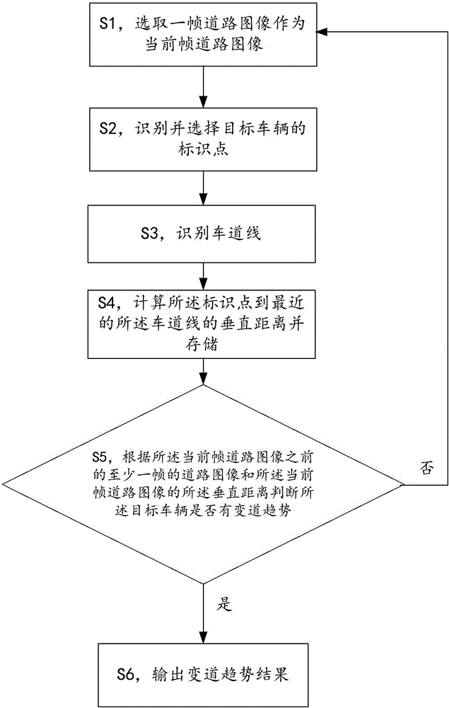
[0018] figure 1 An exemplary flowchart showing a method for judging a vehicle lane-changing tendency according to the first embodiment of the present invention, as shown in figure 1 As shown, the method for judging the lane-changing tendency of the vehicle provided by the first embodiment of the present invention includes: S1, selecting a frame of road image as the current frame of road image; S2, identifying and selecting the identification point of the target vehicle; S3, identifying the lane line ; S4, calculate the vertical distance from the marker point to the nearest lane line and store it; S5, judge whether the target vehicle has a lane-changing tendency according to the road image of at least one frame before the current frame road image and the vertical distance of the current frame road image, if If there is a tendency to change lanes, proceed to step S6; if there is no tendency to change lanes or the trend cannot be judged, proceed to steps S1; S6 to output the resu...

example 1

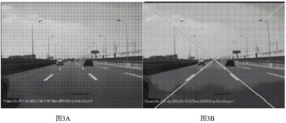
[0057] In this example, the vertex of the angle formed by the target vehicle and the shadow on the ground is used as the identification point of the target vehicle. FIG. 3A-FIG.

[0058] Fig. 3A shows a frame of road image acquired by the image acquisition device, and the intersection line in Fig. 3B indicates the recognized lane line, Figure 3C In , the intersection of the two lines marks the identification point of the target vehicle: the angle vertex formed by the target vehicle and the shadow on the ground, so that a target vehicle in front of the current vehicle is identified through the identification point, rather than through the vehicle's complete The shape recognizes the target vehicle, so that the vehicle can be recognized when the vehicle does not completely appear in front of the current vehicle, so that the lane-changing trend of the vehicle can be judged in time. Figure 3D A diagram showing the vertical distance between the identification point of the target v...

example 2

[0061] In this example, the vertex of the included angle formed by the edge of the vehicle is used as the identification point of the target vehicle. FIG. 4A-FIG. 4F show an example in which the identification point is the vertex of the included angle formed by the edge of the vehicle to determine the lane change of the vehicle.

[0062] Fig. 4A shows a frame of road image acquired by the image acquisition device, the intersection line in Fig. 4B identifies the recognized lane line, Figure 4C In , the intersection of the two lines marks the identification point of the target vehicle: the angle vertex formed by the edge of the target vehicle, so that a target vehicle located in front of the current vehicle is identified through the identification point. Figure 4D A diagram showing the vertical distance between the target vehicle's identification point and the left lane line of the current vehicle in the acquired continuous multi-frame road, where the ordinate is the vertical d...


PUM


Abstract

An embodiment of the invention provides a judgment method and device for lane changing trend of a vehicle and a computer storage medium. The judgment method for the lane changing trend of the vehicle comprises the following steps: selecting a frame of road image as a current frame of road image; recognizing and selecting an identification point of a targeted vehicle; recognizing a lane line; calculating a perpendicular distance from the identification point to the lane line and storing the perpendicular distance; and judging whether the targeted vehicle has the lane changing trend or not according to a perpendicular distance between at least one frame of road image prior to the current frame of road image and the current frame of road image, if the targeted vehicle has the lane changing trend, outputting a lane changing trend result, and if the targeted vehicle does not have the lane changing trend or the lane changing trend cannot be judged, repeating the above steps. According to the embodiment, transverse lane changing trend of the targeted vehicle can be effectively predicted in time, and therefore, danger of lane changing of the targeted vehicle to a current vehicle is avoided effectively.

Description

technical field [0001] Embodiments of the present invention relate to a method for judging a lane-changing tendency of a vehicle, a judging device, and a computer storage medium. Background technique [0002] In the current field of autonomous driving research, target recognition technology is one of the key technologies of autonomous driving technology, and it is also the main source of information input for planning decision-making units and vehicle control units. Therefore, timely and accurate target recognition results can bring great convenience and safety to the subsequent vehicle motion control. In the current commercial autonomous driving technology, the highway application scenario is the entry point for major companies, but the application scenario where the target vehicle suddenly cuts into the lane on the highway has always been one of the challenges in the performance evaluation process of the current automatic driving system . For the target vehicle that sudd...

Claims


Application Information

Patent Timeline
IPC IPC(8): G05D1/02
CPCG05D1/0214G05D1/0223G05D1/0253
Inventor 刘洋李斌
Owner UISEE TECH BEIJING LTD
Learn More