Obtaining an optical transfer function (OTF) from an edge in a sampled image data set

an optical transfer function and image data technology, applied in the field of electrooptical system otf, can solve the problems of increasing uncertainty, increasing uncertainty, and introducing additional errors, and achieve the effect of minimizing the spread of edge response data points

Active Publication Date: 2010-08-24
HARRIS CORP
View PDF2 Cites 13 Cited by
  • Summary
  • Abstract
  • Description
  • Claims
  • Application Information

AI Technical Summary

Benefits of technology

[0017]To meet this and other needs, and in view of its purposes, the present invention provides a method for obtaining a modulation transfer function (MTF) of an electro-optical system using the image of a knife-edge target. The method includes the steps of: (a) obtaining edge response data points, wherein a data point includes a perpendicular distance, d, to the image of the knife-edge target; (b) constructing a sequence of line slopes of the edge response data points, wherein a line slope includes a spread of edge response data points; (c) selecting a line slope that minimizes the spread of edge response data points; (d) calculating the MTF, based on the edge response data points included in the line slope selected in step (c); and (e) providing the MTF to a user. Step (a) includes obtaining the edge response data points, wherein the data point includes an integer intensity value, E, of a pixel corresponding to the data point. The data point is defined by a pair of values of (d, E) of the pixel, and the distance d is a shortest distance between the pixel and the line slope defined as the location of the image of the knife-edge represented by a discrete line. Step (c) includes using least squares regression to minimize the spread of the edge response data points.

Problems solved by technology

Empirical methods, such as trial and error, were often used because of the complexity in making these types of measurements.
Unfortunately, the quantitative accuracy of the MTF is generally accepted to be quite poor, with an uncertainty of 5% or more at the sensor sampling Nyquist spatial frequency, with increasing uncertainty as the spatial frequency approaches the sampling cutoff frequency of the sensor sampling function.
These key features are deemed unnecessary for an inexpensive assessment of spatial performance.
Furthermore, additional error tends to be introduced and the true signal tends to be lost with this process of computing MTF.
As a result, meaningful information may be lost and apparent information, not actually present, may be introduced.
The smoothing performed on the original edge response data, however, introduces error and spurious signal content into the data.
This conventional MTF calculation method does not provide MTF for many spatial frequencies of interest, because of the limited data sample size and spacing.
This adds another source of error beyond those already described, because the available spatial frequencies may not be particularly close together, and the other sources of error from smoothing and numerical differentiation may actually distort the shape of the MTF curve.
These methods of preparing the edge response data by smoothing and resampling, followed by tweaking of the data, and the method of obtaining a pivot point for application of Tatian's method create large errors that cannot be estimated at spatial frequencies as small as 50% of the Nyquist frequency.
Even worse, the data manipulation creates a process that is not generally reproducible.
A hallmark of both conventional methods is that the results are difficult to reproduce and have poor accuracy.
Another major drawback of these methods is sensitivity to the phase of the target and subsequent failure to capture the phase information available in the OTF.
This further complicates obtaining good MTF estimates and adds to the difficulty in obtaining repeatable results.
Without the phase information, the uncertainty beyond the Nyquist frequency quickly becomes unacceptable.
It is this uncertainty which makes cascading MTF curves problematic either in an attempt to isolate individual MTF components, or in combining components to form a complete system model.
Due to the drawbacks and limitations associated with conventional test and calculation methods, MTF is used with the understanding that the error is large and perhaps unacceptable beyond the Nyquist frequency.

Method used


Image

  • Obtaining an optical transfer function (OTF) from an edge in a sampled image data set
  • Obtaining an optical transfer function (OTF) from an edge in a sampled image data set
  • Obtaining an optical transfer function (OTF) from an edge in a sampled image data set

Examples


Embodiment Construction

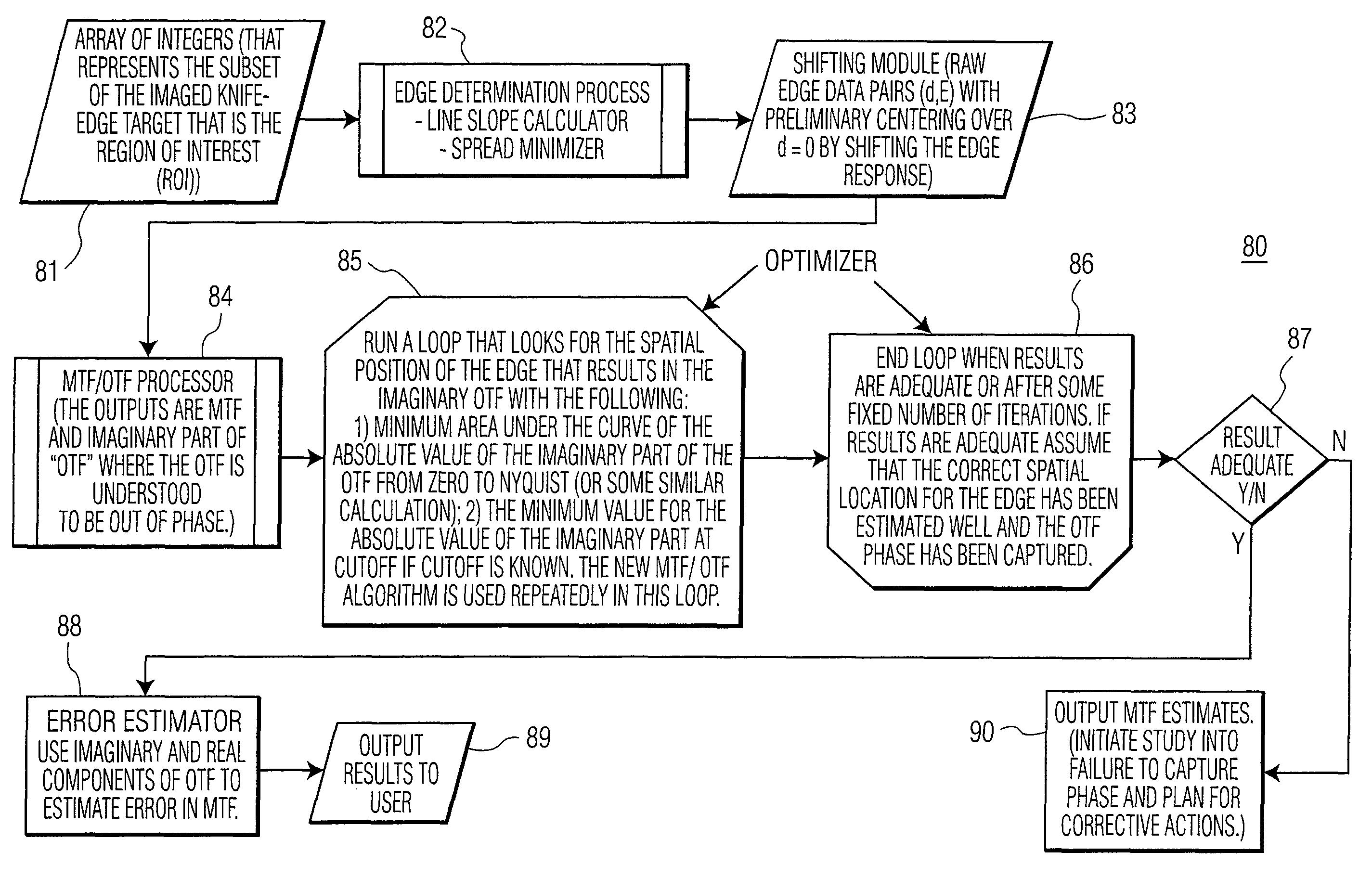
[0034]As will be explained, the present invention estimates an optical transfer function (OTF) of an electro-optical system in a multi-step method using novel algorithms and a knife-edge target. The knife-edge target image is tilted with respect to a focal plane array of the sensor, such that the target includes edges which cross different detector elements at different phases. The target is imaged onto the sensor, and the edge slope and edge response data are derived. The modulation transfer function (MTF) is then estimated directly from this edge response data. Finally, the optical transfer function (OTF) is calculated by finding the correct spatial position of the edge and hence the correct phase component. Error bounds for the MTF are also estimated by the present invention.

[0035]Referring to FIG. 3a, there is shown a system for obtaining knife-edge data, the system generally designated as 30. As shown, a knife-edge target is imaged by a sensor system, which may include any sens...


PUM


Abstract

A method for obtaining a modulation transfer function (MTF) of a knife-edge target imaged by an electro-optical device is described. The method includes the steps of: (a) obtaining edge response data points, where a data point includes a perpendicular distance, d, to the knife-edge target; and (b) constructing a sequence of line slopes of the edge response data points, where a line slope includes a spread of edge response data points. The method then selects a line slope that minimizes the spread of edge response data points, and calculates the MTF, based on the edge response data points included in the selected line slope. The MTF is provided to a user. An edge response data point is defined by a pair of values of (d, E) of a pixel, where distance, d, is the shortest distance between the pixel and a line slope and the pixel has an intensity value, E.

Description

STATEMENT REGARDING FEDERALLY SPONSORED RESEARCH[0001]This invention was made with Government support. The Government has certain rights in the invention.TECHNICAL FIELD[0002]The present invention relates, in general, to a system and method for obtaining an OTF of an electro-optical system. More specifically, the present invention relates to a system and method for measuring an OTF of an electro-optical system using a knife-edge target, calculating edge response data of the target, and determining a modulation transfer function (MTF) directly from the edge response data.BACKGROUND OF THE INVENTION[0003]An electro-optical system converts radiant energy of a particular wavelength or range of wavelengths into an electrical signal that may be used to construct an array of integer values that represents an image. The system usually includes an optical component that focuses radiant energy onto a sensor element. The formed image on the sensing element is converted into a measurable electr...

Claims


Application Information

Patent Timeline
Patent Type & Authority Patents(United States)
IPC IPC(8): G06F19/00
CPCH04N17/002
Inventor LEWIS, CYNTHIA LYNNESACCO, ANDREW P.
Owner HARRIS CORP
Why Eureka
Try Eureka