
Backlight structure of fingerprint module and electronic device

A fingerprint module and backlight structure technology, which is applied in the electronic field, can solve problems such as difficult fingerprint module fingerprint verification operation, monotonous and abrupt fingerprint module settings, and unfavorable user use, so as to improve product perception quality, good backlight effect, and enhance The effect of user experience

Active Publication Date: 2017-05-10
VIVO MOBILE COMM CO LTD
View PDF14 Cites 1 Cited by
  • Summary
  • Abstract
  • Description
  • Claims
  • Application Information

AI Technical Summary

Problems solved by technology

[0004] In the embodiment of the present invention, a backlight structure and electronic equipment of a fingerprint module are provided to solve the monotonous and abrupt setting of the fingerprint module in the prior art, and it is difficult for the user to accurately align the fingerprint module for fingerprint verification operation, which is not conducive to the user , reducing user experience issues

Method used


Image

  • Backlight structure of fingerprint module and electronic device
  • Backlight structure of fingerprint module and electronic device
  • Backlight structure of fingerprint module and electronic device

Examples


Embodiment Construction

[0027] The following will clearly and completely describe the technical solutions in the embodiments of the present invention with reference to the accompanying drawings in the embodiments of the present invention. Obviously, the described embodiments are some of the embodiments of the present invention, but not all of them. Based on the embodiments of the present invention, all other embodiments obtained by persons of ordinary skill in the art without creative efforts fall within the protection scope of the present invention.

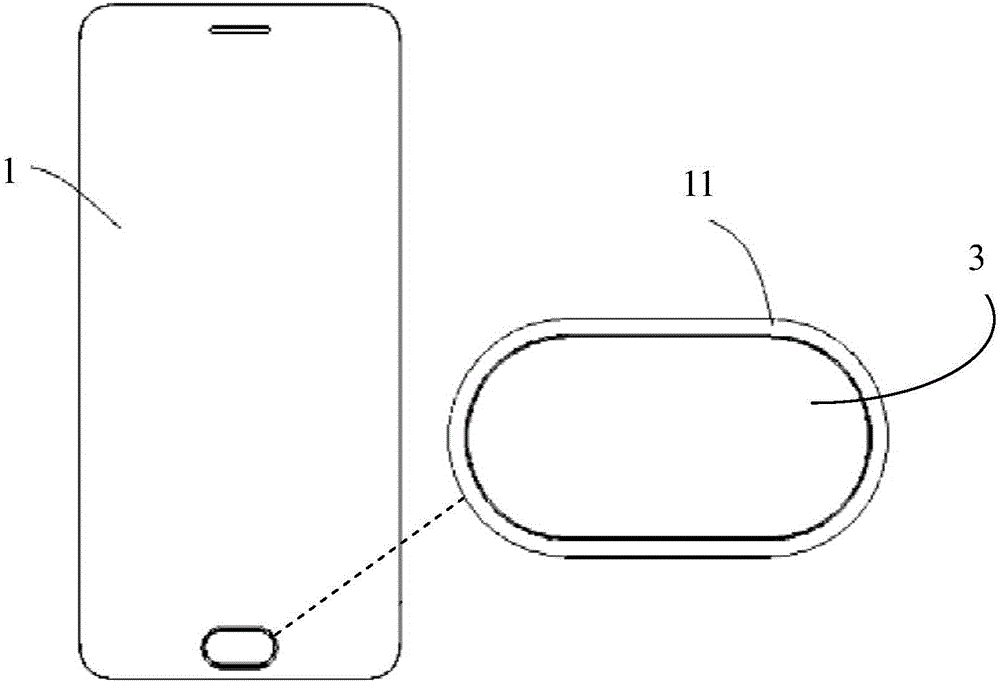
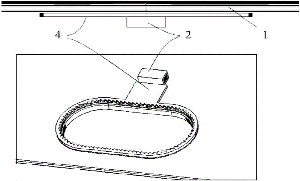
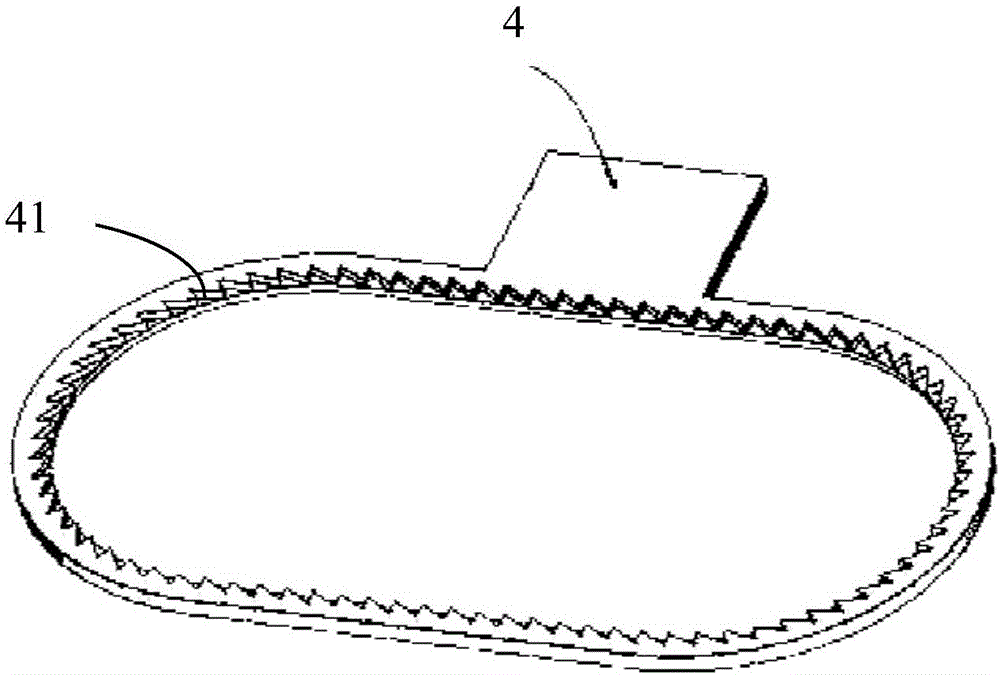
[0028] combine figure 1 , figure 2 As shown, the embodiment of the present invention discloses a backlight structure of a fingerprint module, including:

[0029] The cover plate 1, the light source device 2 covered under the first surface of the cover plate 1, and the fingerprint module 3 penetrating through the cover plate 1 and exposed on the second surface of the cover plate 1, the first surface and the second surface are towards the opposite sid...


PUM

PropertyMeasurementUnit
Thicknessaaaaaaaaaa

Abstract

The present invention provides a backlight structure of a fingerprint module and an electronic device. The backlight structure comprises a cover plate, a light source device covered below the first surface of the cover plate, and a fingerprint module configured to pass through the cover plate and exposed to the second surface of the cover plate. The first surface and the second surface are opposite in orientation. The edge of the cover plate, which surrounds the fingerprint module, is provided with a first region. The first region is a light-transmitting region. The cover plate below the first region is provided with a light guiding device used for guiding the light emitted from the light source device. The light guiding device is arranged at the outer circumference of the fingerprint module. The projection area of the light guiding device on the cover plate covers the first region, so that the guided light is enabled to pass through the first region to be outputted to the second surface of the cover plate. Therefore, the above structure is good in backlight effect, and the product quality is improved. The user experience is also improved.

Description

technical field [0001] The invention relates to the field of electronic technology, in particular to a backlight structure of a fingerprint module and electronic equipment. Background technique [0002] With the development of the mobile phone, tablet computer and other electronic equipment industries and markets, users have higher requirements for product privacy and password exclusivity, and fingerprint modules in electronic product configurations have gradually become standard components. [0003] In electronic products, such as mobile phones, the fingerprint module is generally placed in the middle of the back or under the front of the electronic product, and the user touches the fingerprint module with a finger to complete the process of fingerprint identification and verification. However, the existing fingerprint module is directly installed on the cover plate of the mobile phone, which often does not have a backlight effect, which is monotonous and abrupt, and when t...

Claims


Application Information

Patent Timeline
IPC IPC(8): G06K9/00G06K9/20G06F1/16
CPCG06F1/1684G06F1/1626G06V40/13G06V10/141
Inventor 黄攀彭义军
Owner VIVO MOBILE COMM CO LTD
Learn More