
Mounting parameter calibration method for vehicular camera of driving assistant system

A technology for driving assistance systems and installation parameters, applied in image data processing, image analysis, instruments, etc., can solve problems such as inconvenient operation, camera tolerance, inaccurate calibration results, etc., to achieve low equipment and equipment costs, and avoid calibration errors. , the effect of convenient operation

Active Publication Date: 2017-05-10
清华大学苏州汽车研究院(吴江)
View PDF7 Cites 11 Cited by
  • Summary
  • Abstract
  • Description
  • Claims
  • Application Information

AI Technical Summary

Problems solved by technology

[0005] 1. It is not easy to accurately determine the position of the calibration plate relative to the vehicle, and the resulting error will lead to inaccurate calibration results
[0006] 2. There are also tolerances in the manufacture of cameras of the same batch. When installing in batches, there will be errors in applying the internal reference results of one calibration to other cameras
[0007] 3. According to the different installation positions of passenger cars and commercial vehicles, the requirements for the calibration plate are different. For commercial vehicles, a larger size calibration plate is required, which is inconvenient to operate
[0008] 4. The projection conversion from perspective view to top view cannot be effectively completed
Therefore, the exact position of the vehicle in the lane cannot be obtained

Method used


Image

  • Mounting parameter calibration method for vehicular camera of driving assistant system
  • Mounting parameter calibration method for vehicular camera of driving assistant system
  • Mounting parameter calibration method for vehicular camera of driving assistant system

Examples


Embodiment

[0042] The preferred embodiments of the present invention will be further described below in conjunction with the accompanying drawings.

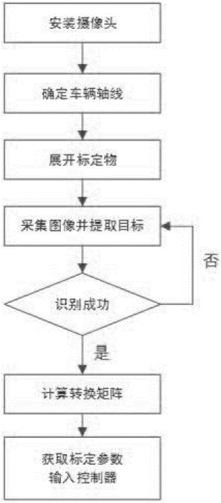
[0043] Such as figure 1 As shown, the specific operation is as follows:

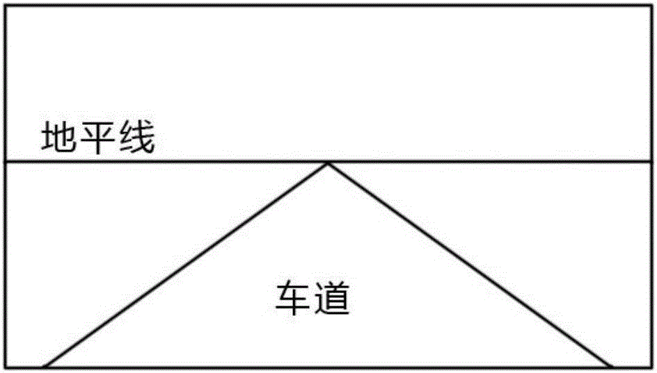
[0044] 1. Determine the installation position and angle of the camera. Adjust the horizon line in the picture to a suitable position, such as figure 2 , so that the horizon remains horizontal in the frame. The preferred position of the camera is in the middle of the car, and the height from the ground can be adjusted according to the vehicle model. The recommended distance is 1.2-1.5m for small vehicles and 1.5-2.2m for large vehicles such as trucks.

[0045] 2. Determine the position of the central axis at the front and rear of the vehicle through features such as the fixed point of the vehicle license plate, and use the plumb bob to extend the midpoint to the ground plane.

[0046] Determine the centerline of the vehicle using auxiliary bulkheads and a laser p...


PUM


Abstract

The invention discloses a mounting parameter calibration method for a vehicular camera of a driving assistant system. The method comprises the steps of collecting calibration images and extracting HSV of the images; for a V channel, generating thresholds for segmented images through utilization of a maximum between-class variance method, carrying out binarization processing on the images, and screening and segmenting calibration object areas through the binarized images, thereby obtaining an initial selection area of each calibration object; extracting edge features of the calibration objects, thereby obtaining edge images, processing the edge images, and determining the pixel positions of the calibration objects in the images through combination of a geometric constraint relationship between the initial selection binarized image information of the calibration objects and the placement of the calibration objects; calculating a projection matrix and an inverse projection matrix of the projection matrix according to image coordinates and physical coordinates of the calibration objects; and writing a calibration result into a controller. According to the calibration method, the cost of required devices is relatively low, the calibration method is applicable to batch mounting of various vehicles and is compatible with different heights and photographing angles, and an error resulting from size mismatch of calibration plates is avoided.

Description

technical field [0001] The invention belongs to the technical field of automotive electronics, and in particular relates to a method for calibrating installation parameters of a vehicle-mounted camera used in a driving assistance system, which can be applied to batch installation. Background technique [0002] Using computer vision technology to collect the driving environment, identify the types of obstacles and measure the distance and speed can effectively realize the driving assistance function and ensure the driving safety of the driver. [0003] In order to accurately measure the relative position and relative velocity with the obstacles in front, it is necessary to calibrate the installation parameters of the front-view camera and establish the conversion relationship between the image coordinate system and the world coordinate system. [0004] At present, the commonly used camera calibration method mainly adopts a fixed-position calibration plate for calibration. Th...

Claims


Application Information

Patent Timeline
IPC IPC(8): G06T7/80
Inventor 陈睐张伟刘星
Owner 清华大学苏州汽车研究院(吴江)
Learn More