
switch structure

A technology of switch structure and transmission structure, applied in the field of switch structure, can solve problems such as poor coordination of mechanical characteristics of circuit breakers, and achieve the effects of good coordination, increased safety distance, and easy use and maintenance.

Active Publication Date: 2019-03-22
ZHEJIANG HUAYI ELECTRIC APPLIANCE TECH
View PDF8 Cites 0 Cited by
  • Summary
  • Abstract
  • Description
  • Claims
  • Application Information

AI Technical Summary

Problems solved by technology

[0004] The main purpose of the present invention is to provide a switch structure to solve the problem in the prior art that the operating mechanism is located on the side of the primary circuit, resulting in poor coordination of the mechanical characteristics of the circuit breaker

Method used


Image

  • switch structure
  • switch structure
  • switch structure

Examples


Embodiment Construction

[0022] The technical solutions of the present invention will be clearly and completely described below in conjunction with the accompanying drawings. Apparently, the described embodiments are some of the embodiments of the present invention, but not all of them. Based on the embodiments of the present invention, all other embodiments obtained by persons of ordinary skill in the art without making creative efforts belong to the protection scope of the present invention.

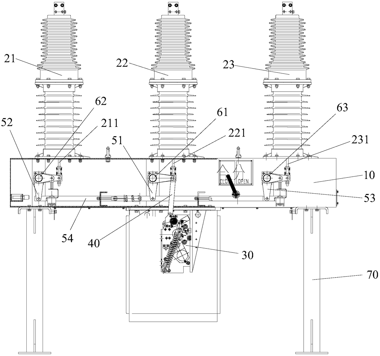
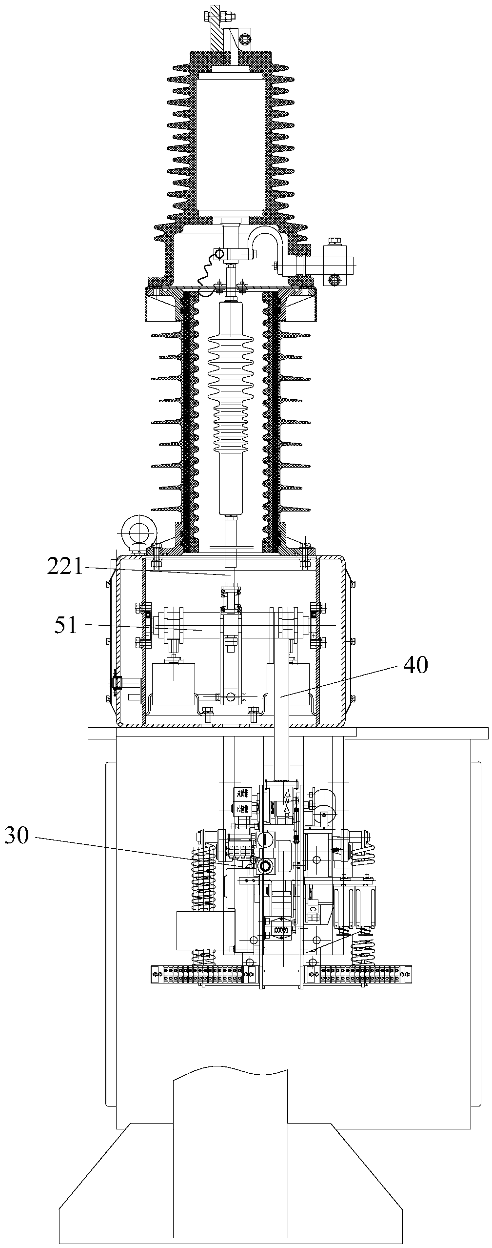
[0023] like figure 2 and image 3 As shown, the switch structure of this embodiment includes: housing 10, A-phase pole 21, B-phase pole 22, C-phase pole 23, operating mechanism 30 and transmission structure, A-phase pole 21, B-phase pole 22 and C-phase poles 23 are arranged above the casing 10 at intervals; the operating mechanism 30 is arranged below the casing 10, the operating side of the operating mechanism 30 is located on the side where the side of the casing 10 is located, and the output end of the op...


PUM


Abstract

The invention provides a switch structure. The switch structure comprises a shell; an A phase pole column, a B phase pole column and a C phase pole column, the A phase pole column, the B phase pole column and the C phase pole column are arranged above the shell at intervals; the switch structure further comprises: an operating mechanism arranged below the shell, wherein an operating side of the operating mechanism is located on one side where a side face of the shell is located, an output end of the operating mechanism is in driving connection with a B phase pull rod of the B phase pole column, and the up and down movement of the output end drives the up and down movement of the B phase pull rod; and a transmission mechanism used for connecting the B phase pull rod with an A phase pull rod of the A phase pole column and a C phase pull rod of the C phase pole column, wherein the transmission mechanism is driven by the B phase pull rod to drive the A phase pull rod and the C phase pull rod to move up and down together with the B phase pull rod. The technical scheme of the invention effectively solves the problem of poor mechanical property coordination of a circuit breaker resulting from that the operating mechanism is located on the side face of a primary loop in the prior art.

Description

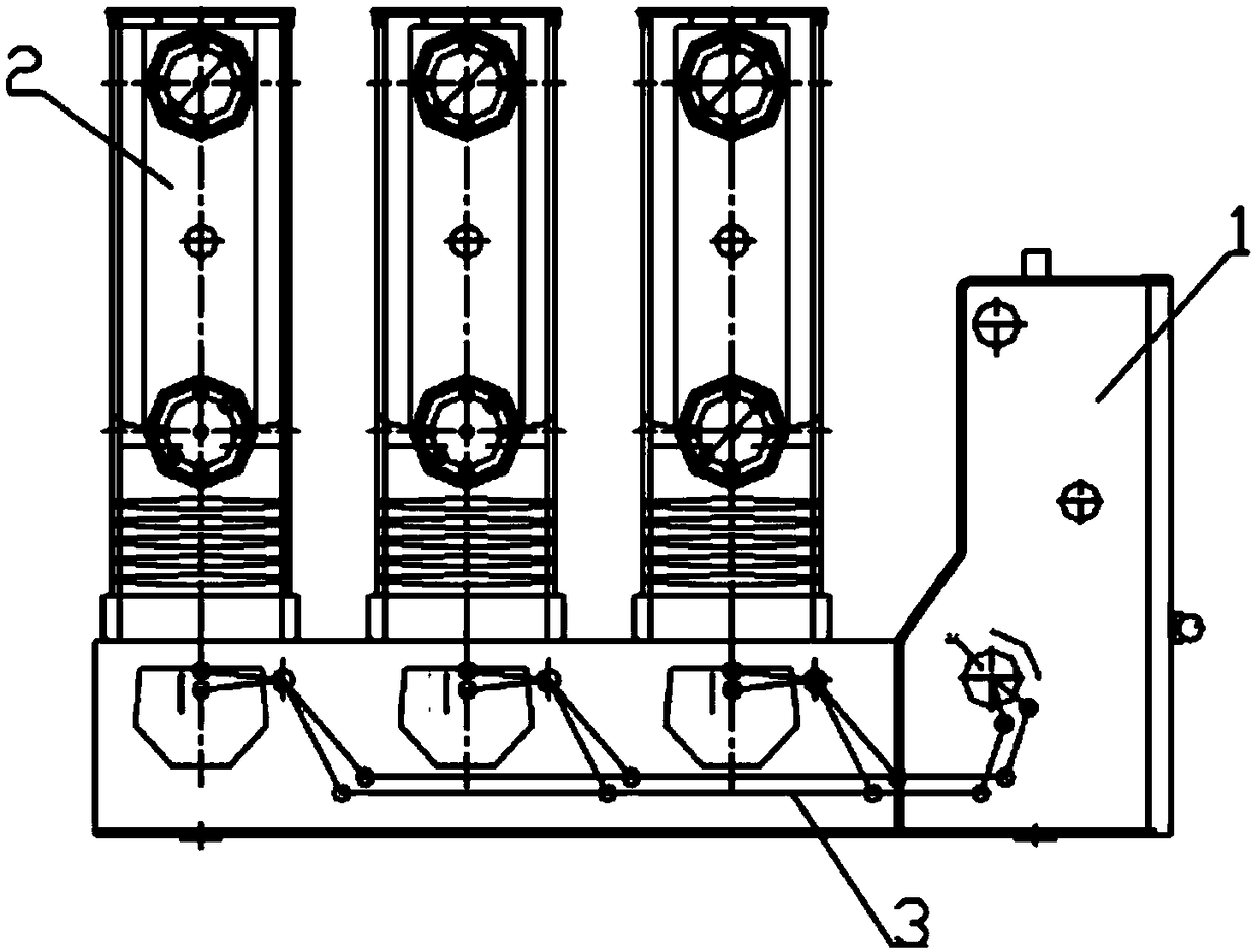
technical field [0001] The invention relates to the technical field of electrical equipment, in particular to a switch structure. Background technique [0002] Currently, if figure 1 As shown, the circuit breaker includes frame 1 and three-phase poles A, B, and C of the primary circuit 2. The frame 1 has a closing energy storage operating mechanism and an opening operating mechanism, and the three-phase poles of A, B, and C of the primary circuit 2 The poles are arranged longitudinally, and the closing energy storage operating mechanism and the opening operating mechanism simultaneously perform opening and closing operations on the A, B, and C three-phase poles through a pair of main crank arms 3 . [0003] Since the closing energy storage operating mechanism and the opening operating mechanism are located on the side of the primary circuit 2, the closer to the closing energy storing operating mechanism and the opening operating mechanism, the faster the closing speed, open...

Claims


Application Information

Patent Timeline
Patent Type & Authority Patents(China)
IPC IPC(8): H01H3/46
CPCH01H3/46
Inventor 李彬
Owner ZHEJIANG HUAYI ELECTRIC APPLIANCE TECH
Learn More