Self-locking U-shaped wire clamp

A U-shaped, wire clip technology, applied in the installation of electrical components, cables, overhead installation, etc., can solve the problems of loosening, binding method and binding tightness without a unified standard, large randomness, etc.

Active Publication Date: 2017-05-10
广州勇艺邦电子科技有限公司
View PDF7 Cites 5 Cited by
  • Summary
  • Abstract
  • Description
  • Claims
  • Application Information

AI Technical Summary

Problems solved by technology

The traditional street code consists of a hardware bracket that can be nailed to the wall (the hardware bracket includes a base that can be fixed to the wall and a bracket that can be fixed with a binding wire), a porcelain lug for supporting cables, and a porcelain lug for fixing the porcelain lug to the hardware. The cable on the bracket is composed of wires. When the cable crosses the street, it is generally close to the porcelain, and then the cable and the porcelain are bound and fixed by winding the cable. This kind of street code is inefficient, and the binding method and binding tightness are not uniform. Standard, large randomness, easy to cause loose wires, loose or even loose after long-term use, usually use thinner metal wires such as aluminum wires, which are directly wound on the cable sheath, which will cause damage to the cable sheath , it is easy to cause dangers such as cable overheating or even leakage short circuit, and the insulated cable will be in direct contact with the metal wire, resulting in potential leakage
[0003]The existing technology has improved the traditional cable fixing method, and the cable is fixed on the porcelain by using the clamp, but these clamps generally adopt the method of bolts and nuts To connect, when working at heights, it is time-consuming and labor-intensive for a single person to operate

Method used


Image

  • Self-locking U-shaped wire clamp
  • Self-locking U-shaped wire clamp

Examples


Embodiment Construction

[0021] A self-locking fastening clamp of the present invention will be further described below in conjunction with the accompanying drawings:

[0022] It should be noted that the terms "upper", "lower", "front", "rear" and similar expressions used in this specification are only for the purpose of illustration, and are determined according to the actual situation in the embodiment; "Porcelain Lu" can be selected from the current common street code porcelain or similar structures.

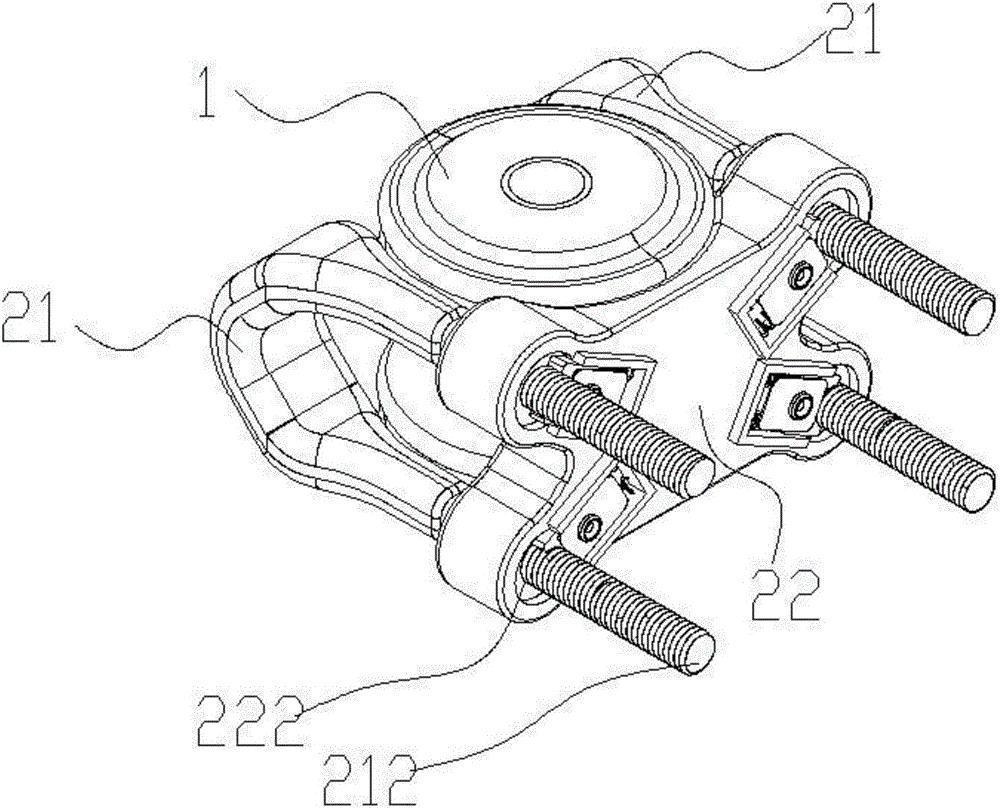
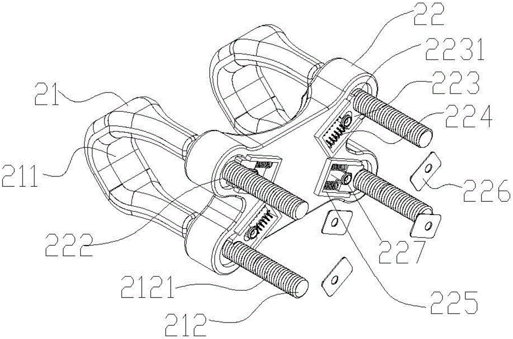
[0023] Such as Figure 1-2 As shown, a self-locking U-shaped wire clip includes a splint 22 and at least two U-shaped clips 21. The bending part of the U-shaped clip 21 is a clamping part 211, and the rods on both sides are locking rods 212. The splint 22 There are at least two pairs of locking holes 222 corresponding to the locking rods 212, at least two U-shaped clamps 21 are parallel and the locking rods 212 are vertically passed through the locking holes 222 on the splint 22 respectively. There...


PUM


Abstract

A self-locking U-shaped wire clamp comprises a clamping plate and at least two U-shaped clamps, wherein wire clamping parts are arranged at bending positions of the U-shaped clamps, two side rods are locking rods, at least two pairs of locking holes corresponding to the locking rods are formed in the clamping plate, the U-shaped clamps are in parallel, the locking rods respectively and perpendicularly penetrate through the locking holes in the clamping plate, non-return valve teeth are arranged on the locking rods, movable locking blocks are arranged at side edges of the locking holes, locking teeth matched with the non-return valve teeth are arranged on the locking blocks, and the other ends prop against locking springs. During operation, the clamping plate is attached onto one side of a porcelain disc, a cable is attached onto the other side of the porcelain disc, the self-locking U-shaped wire clamp is automatically locked after the U-shaped clamps are inserted into the clamping plate, so that the cable is locked on the porcelain disc and is not liable to loose; and when the self-locking U-shaped wire clamp is needed to be opened, only the locking springs are needed to be pressed to make the locking blocks retrieved, the U-shaped clamps can be freely taken out of the clamping plate, so that the cable is loosen, the self-locking U-shaped wire clamp is very convenient to operate and use and is particularly and suitably used for overhead cable construction.

Description

technical field [0001] The invention relates to the field of cable installation, in particular to a self-locking U-shaped cable clamp. Background technique [0002] The street code is a device used to straighten and fix the cable when erecting the cable. The traditional street code consists of a hardware bracket that can be nailed to the wall (the hardware bracket includes a base that can be fixed to the wall and a bracket that can be fixed with a binding wire), a porcelain lug for supporting cables, and a porcelain lug for fixing the porcelain lug to the hardware The cable on the bracket is composed of wires. When the cable crosses the street, it is generally close to the porcelain, and then the cable and the porcelain are bound and fixed by winding the wire. This kind of street code is inefficient, and the binding method and binding tightness are not uniform. Standard, large randomness, easy to cause loose wires, loose or even loose after long-term use, usually use thin m...

Claims


Application Information

Patent Timeline
Patent Type & Authority Applications(China)
IPC IPC(8): H02G7/05
CPCH02G7/056
Inventor 李孔形陈炳祥陆刘生张利新刘碧莲吴先进杜小建刘丽娟梁文军蔡克诚陈敬江
Owner 广州勇艺邦电子科技有限公司
Why Eureka
Try Eureka