Anti-PID (Potential Induced Degradation) combiner box system and realization method thereof

A realization method and combiner box technology, applied in photovoltaic power generation, photovoltaic modules, electrical components, etc., can solve the problems of scattered layout, difficult wiring, large number of combiner boxes, etc., and achieve the effect of reducing construction costs and reducing production

Active Publication Date: 2017-05-10
广东兆能新能源有限公司
View PDF10 Cites 16 Cited by
  • Summary
  • Abstract
  • Description
  • Claims
  • Application Information

AI Technical Summary

Problems solved by technology

In addition, due to the large number of combiner boxes and scattered layout, especially the addition of anti-PID equipment in the original photovoltaic power ...

Method used


Image

  • Anti-PID (Potential Induced Degradation) combiner box system and realization method thereof
  • Anti-PID (Potential Induced Degradation) combiner box system and realization method thereof
  • Anti-PID (Potential Induced Degradation) combiner box system and realization method thereof

Examples


Embodiment Construction

[0032] The present invention provides an anti-PID combiner box system and its implementation method. In order to make the purpose, technical solution and effect of the present invention clearer and clearer, the present invention will be further described in detail below with reference to the accompanying drawings and examples. It should be understood that the specific embodiments described here are only used to explain the present invention, not to limit the present invention.

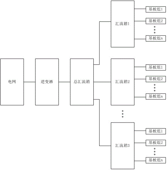
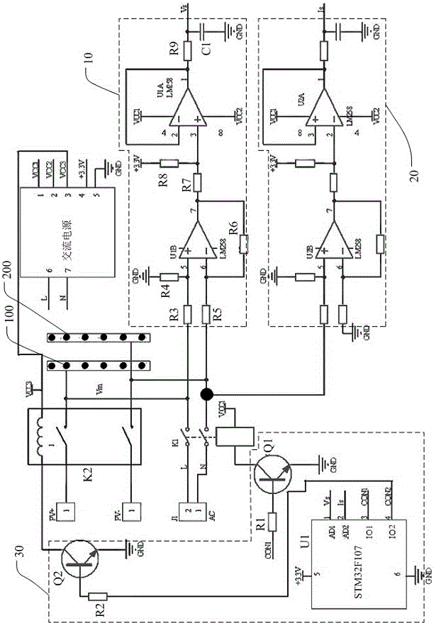
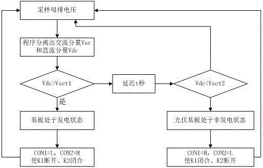
[0033] The anti-PID combiner box system of the present invention is used to prevent the performance decline of the photovoltaic power generation system due to the PID effect; wherein, the anti-PID combiner box system includes: a total combiner box and anti-PID equipment; figure 2 As shown, the inside of the general combiner box is provided with a single-phase AC input port J1 for connecting single-phase AC power, a positive and negative bus bar 100 for connecting a DC cable output by the combiner box, ...


PUM


Abstract

The invention discloses an anti-PID (Potential Induced Degradation) combiner box system and a realization method thereof. The anti-PID combiner box system comprises a general combiner box; the general combiner box is internally provided with a positive bus and a negative bus connected with a DC cable for output of a combiner box and a first switching device; the positive bus and the negative bus are respectively connected with the input end of an inverter through a positive input port and a negative input port; a single-phase AC input port is connected with the positive bus and the negative bus through the first switching device for loading the AC to the positive bus and the negative bus of the general combiner box through closing the first switching device and transmitting the AC to each combiner box through the DC cable. In the scheme of the invention, the AC and the DC use the existing cable in different time periods, putting into production of an AC cable is reduced, and the power station construction cost is reduced.

Description

technical field [0001] The invention relates to the technical field of photovoltaic power generation, in particular to an anti-PID combiner box system and an implementation method thereof. Background technique [0002] Such as figure 1 As shown, the DC side of the current high-power photovoltaic power generation system usually connects the outputs of multiple photovoltaic substrate strings (as shown in the figure, substrate group 1, substrate group 2...substrate group n) to the combiner box through cables. The first combiner box is connected to the main combiner box (also known as DC cabinet) through cables, and the main combiner box is usually placed near the inverter and connected to the grid through the inverter. When the photovoltaic substrate generates electricity during the day, the electric energy generated by the photovoltaic substrate is transmitted to the combiner box through the cable, and then the combiner box transmits the electric energy to the general combine...

Claims


Application Information

Patent Timeline
IPC IPC(8): H02S40/34H02S40/32H02J9/08
CPCH02J9/08H02S40/32H02S40/34Y02B10/70Y02E10/50
Inventor 郑照红
Owner 广东兆能新能源有限公司
Why Eureka
Try Eureka