Reluctance Adjustment Method of Generator

An adjustment method and generator technology, applied in magnetic circuits, electromechanical devices, electrical components, etc., can solve the problems of unstable clean power generation energy, impeding rotor rotation, and exhaustion

Active Publication Date: 2020-12-04
温岭绿能新能源有限公司
View PDF4 Cites 0 Cited by
  • Summary
  • Abstract
  • Description
  • Claims
  • Application Information

AI Technical Summary

Problems solved by technology

[0002] Power generation refers to the production process of converting raw energy such as water energy, thermal energy of petrochemical fuels (coal, oil, natural gas), nuclear energy, etc., into electric energy by using power generation devices to supply the needs of various departments of the national economy and people's lives. Now Power generation still uses fossil fuels as the main form of power generation, but the resources of fossil fuels are not many and are becoming increasingly exhausted. Human beings have gradually begun to use some clean natural energy sources such as solar energy, wind energy, geothermal energy, and ocean energy for power generation, but these Clean power generation energy is not stable enough. For example, wind energy varies from time to time, ocean wave energy varies from time to time, and the light energy generated by solar energy in different time periods is inconsistent, etc. All these factors affect the power generation work. When the natural energy is weakened, the motor The counter electromotive force generated during the power generation process of the main body will hinder the rotation of the rotor, so that the main body of the motor stops generating power. For this reason, the inventor has designed a power generation device that can automatically adjust the distance between the coil and the magnet inside the main body of the motor, so that The main body of the motor can still perform power generation work when the natural energy is weakened

Method used


Image

  • Reluctance Adjustment Method of Generator
  • Reluctance Adjustment Method of Generator
  • Reluctance Adjustment Method of Generator

Examples


Embodiment Construction

[0042] A reluctance adjustment method for a generator, the steps of which are:

[0043] (1) The natural energy weakening stage;

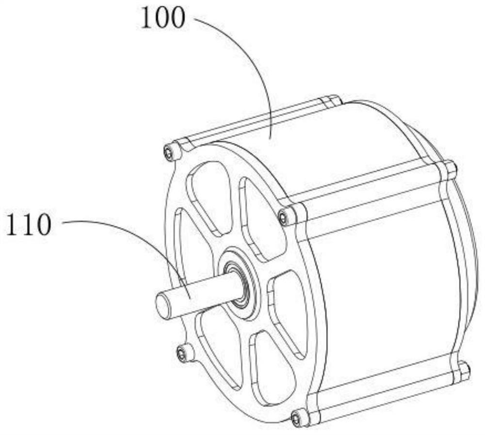
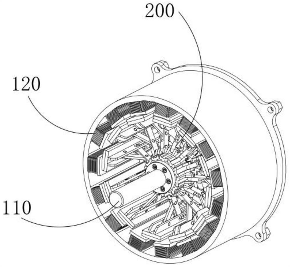
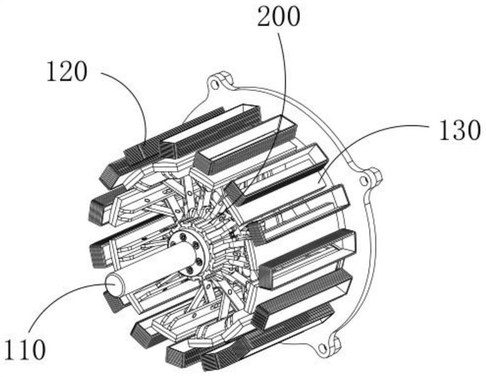
[0044] S1: When the external natural energy weakens, the rotation speed of the rotating shaft 110 of the motor body 100 decreases, and the internal components of the centrifugal drive mechanism 300 change;

[0045] The centrifugal drive mechanism 300 includes a centrifugal member 310 and a driving member 320. The centrifugal member 310 includes a fixed block 311 and a roller 313. The fixed block 311 is a cylindrical structure and the fixed block 311 is coaxially fixed on the outside of the rotating shaft 110. The fixed block 311 The outer surface of the centrifugal piece is provided with three groups along the circumferential direction of the rotating shaft 110. The centrifugal piece includes a guide block and a roller 313. The guide block is fixed on the fixed block 311 and the extension direction of the guide block is in line with the fixed block ...


PUM


Abstract

The invention discloses a method for adjusting the magnetic resistance of a generator, which comprises the following steps: when external natural energy is weakened, the rotating speed of a rotating shaft of a motor body is reduced, and a roller moves close to a fixed block along the guide direction of a guide groove; the elastic force of a separation spring drives a first triggering component anda driving component to move away from a second triggering component; a first connecting rod and a second connecting rod are matched and drive a mounting plate to move close to the rotating shaft to increase the distance between a magnet and a coil and reduce the distance between the magnet and the rotating shaft, the increase in distance between the magnet and the coil causes reduction in counterelectromotive force generated in the power generation process, the reduction in distance between the magnet and the rotating shaft causes reduction in resistance borne by the rotating shaft during rotation under the action of the same natural energy, and the two effects work together to enable the motor body to still generate power under the condition that the natural energy is weakened; and whenthe external natural energy recovers, the increase in rotating speed of the rotating shaft and the reduction in distance between the magnet and the coil are restored to the original states, and the normal power generation of the motor body is not influenced.

Description

technical field [0001] The invention relates to the field of power generation, in particular to a power generation method utilizing natural energy. Background technique [0002] Power generation refers to the production process of converting raw energy such as water energy, petrochemical fuel (coal, oil, natural gas) heat energy, nuclear energy, etc. into electric energy by using a power generation device to supply the needs of various departments of the national economy and people's lives. Now Power generation still uses fossil fuels as the main form of power generation, but the resources of fossil fuels are not many and are becoming increasingly exhausted. Human beings have gradually begun to use some clean natural energy such as solar energy, wind energy, geothermal energy, and ocean energy to generate electricity. Clean power generation energy is not stable enough, for example, wind energy fluctuates from time to time, ocean wave energy varies from time to time, and the ...

Claims


Application Information

Patent Timeline
Patent Type & Authority Patents(China)
IPC IPC(8): H02K1/27
CPCH02K1/274H02K2201/03H02K2213/09
Inventor 张继美杨洪开
Owner 温岭绿能新能源有限公司
Why Eureka
Try Eureka