Eureka AIR delivers breakthrough ideas for toughest innovation challenges, trusted by R&D personnel around the world.

Wind power generation device utilizing wind energy of factory equipment and using method of wind power generation device

A technology for wind power generation equipment and factory equipment, which is applied to wind power generation, wind turbines, and wind turbine combinations, etc., can solve the problems of inability to make full use of factory equipment, inconvenient replacement of fan blades, and easy damage to wind power generation equipment.

Inactive Publication Date: 2021-12-31
重庆锦森腾建筑工程咨询有限公司
View PDF0 Cites 0 Cited by
  • Summary
  • Abstract
  • Description
  • Claims
  • Application Information

AI Technical Summary

Problems solved by technology

[0005] In view of this, in order to solve the problem that the wind power generation device at the air exhaust outlet of the existing workshop is easily damaged, it is inconvenient to replace the fan blades, and the wind energy cannot be fully utilized by the factory equipment, resulting in waste of resources, it provides a wind power generator that utilizes the wind energy of the factory equipment. Wind power generation device and method of use thereof

Method used


Image

  • Wind power generation device utilizing wind energy of factory equipment and using method of wind power generation device
  • Wind power generation device utilizing wind energy of factory equipment and using method of wind power generation device
  • Wind power generation device utilizing wind energy of factory equipment and using method of wind power generation device

Examples


Embodiment 1

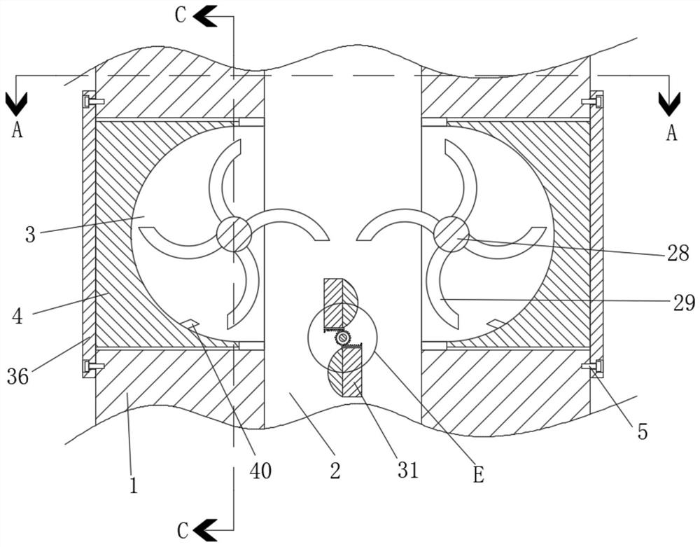
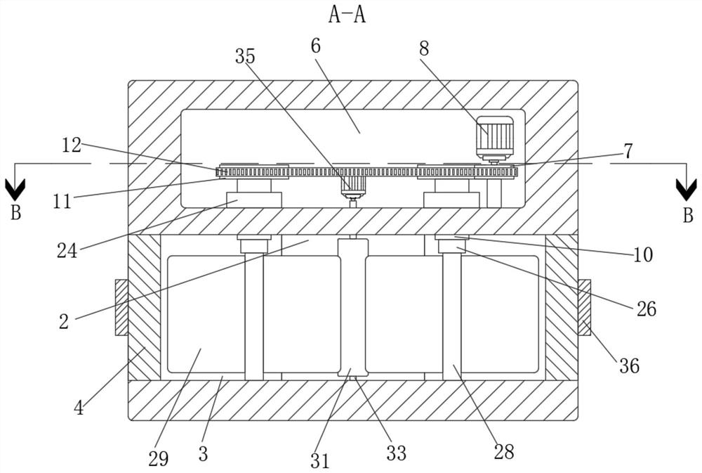
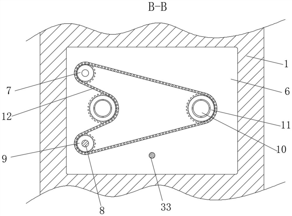
[0043] Such as Figure 1-7 The shown a kind of wind power generation device that utilizes the wind energy of factory equipment includes an exhaust pipe 1, and an air vent 2 is arranged in the exhaust pipe 1, and two symmetrical sliding grooves 3 are arranged in the exhaust pipe 1, and two The sliding grooves 3 are all in communication with the air vent 2, and the sliding groove 3 is slidingly connected with an arc-shaped plate 4, and the side of the arc-shaped plate 4 away from the air vent 2 is fixedly connected with a connecting plate 36, and a plurality of bolts are arranged in the connecting plate 36 5, and one end of a plurality of bolts 5 close to the vent 2 is threadedly connected with the exhaust pipe 1, and the exhaust pipe 1 is provided with a placement slot 6, and the inner wall of the placement slot 6 near the vent 2 rotates through and connects two The rotating shaft 10 is relatively symmetrical, and the end of the rotating shaft 10 close to the vent 2 extends int...

Embodiment 2

[0056] This embodiment is a further improvement of the previous embodiment, such as Figure 1-8As shown, a wind power generation device utilizing wind energy of factory equipment includes an exhaust duct 1, an air vent 2 is arranged in the exhaust duct 1, two symmetrical sliding grooves 3 are arranged in the exhaust duct 1, and two The sliding grooves 3 are all in communication with the air vent 2, and the sliding groove 3 is slidingly connected with an arc-shaped plate 4, and the side of the arc-shaped plate 4 away from the air vent 2 is fixedly connected with a connecting plate 36, and a plurality of bolts are arranged in the connecting plate 36 5, and one end of a plurality of bolts 5 close to the vent 2 is threadedly connected with the exhaust pipe 1, and the exhaust pipe 1 is provided with a placement slot 6, and the inner wall of the placement slot 6 near the vent 2 rotates through and connects two The rotating shaft 10 is relatively symmetrical, and the end of the rotat...


PUM


Abstract

The invention relates to a wind power generation device utilizing wind energy of factory equipment. Two symmetrical sliding grooves are formed in an exhaust pipe, a connecting plate is fixedly connected to the side, away from a ventilation opening, of an arc-shaped plate in the sliding grooves, and the ends, close to the ventilation opening, of a plurality of bolts in the connecting plate are all in threaded connection with the exhaust pipe; the inner wall of the side, close to the ventilation opening, of the containing groove in the exhaust pipe is rotationally connected with two symmetrical rotating shafts in a penetrating mode, the inner wall of the containing groove is rotationally connected with a first chain wheel, the bottom of the containing groove is fixedly connected with a second chain wheel, the outer walls of the two rotating shafts are fixedly sleeved with third chain wheels, and a control assembly is arranged in the containing groove; and a first rotating shaft rotationally connected with the inner wall of one side of the sliding groove is arranged in the rotating shaft, the outer wall of the first rotating shaft is connected with a plurality of air gathering fans, and a replacing assembly used for replacing the first rotating shaft and the air gathering fans is arranged in the rotating shaft. The problems that an existing wind power generation device at an air outlet of a workshop is prone to damage, fan blades are inconvenient to replace, factory equipment cannot be fully utilized to generate wind energy, and resources are wasted are solved.

Description

technical field [0001] The invention belongs to the technical field of wind power generation, and relates to a wind power generation device utilizing wind energy of factory equipment and a use method thereof. Background technique [0002] With the popularization of environmental protection knowledge, all walks of life regard energy conservation and environmental protection as important development directions. Wind power generation uses wind energy to generate electricity, with low power generation cost and convenient equipment maintenance. It is widely used in various small power generation occasions to save electric energy. [0003] In the field of industrial production, the factory workshop is generally relatively wide, and the staff and production machinery are located in the workshop at the same time, which may easily lead to turbid air in the workshop and imbalance of temperature and humidity, which will not only affect the health of the staff but also affect the operat...

Claims


Application Information

Patent Timeline
IPC IPC(8): F03D9/25F03D9/45F03D80/00
CPCF03D9/25F03D9/45F03D80/00Y02E10/72Y02E10/728Y02B10/30
Inventor 戚秀芝周毅
Owner 重庆锦森腾建筑工程咨询有限公司
Why Eureka
Eureka Blog
Learn More