Automatic access circuit of CAN bus terminal resistor

A CAN bus and terminal resistance technology, applied in the field of CAN bus, can solve the problems of abnormal communication, error-prone, low efficiency, etc., and achieve the effect of simplifying the installation process and improving reliability

Pending Publication Date: 2017-05-10
DONGGUAN LILONG BATTERY TECH CO LTD
View PDF4 Cites 8 Cited by
  • Summary
  • Abstract
  • Description
  • Claims
  • Application Information

AI Technical Summary

Problems solved by technology

This manual method often needs to be carried out after the system is install

Method used


Image

  • Automatic access circuit of CAN bus terminal resistor

Examples


Embodiment Construction

[0011] The present invention and its beneficial effects will be further described in detail below in conjunction with specific embodiments, however, the specific embodiments of the present invention are not limited thereto.

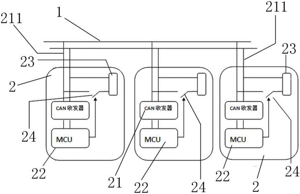
[0012] Such as figure 1 As shown, a CAN bus terminal resistor is automatically connected to the circuit, including a bus cable 1 and a CAN transceiver node 2 that accesses the bus cable 1. The CAN transceiver node 2 is at least two, and the CAN transceiver node 2 includes CAN Transceiver, control unit, terminal resistance 23 and resistance switch 24, described CAN transceiver point leads to have access line 211, and described CAN transceiver accesses bus cable 1 through described access line 211, and described terminal The resistor 23 is connected in series with the resistor switch 24 and connected to the access line 211 , and the control unit can control the resistor switch 24 to be closed. Wherein, the resistance value of the terminal resistor 23 is 12...


PUM

PropertyMeasurementUnit
Resistanceaaaaaaaaaa

Abstract

The invention belongs to the technical field of CAN buses, and specifically relates to an automatic access circuit of a CAN bus terminal resistor. The automatic access circuit comprises a bus cable and CAN transceiver nodes accessing the bus cable, at least two CAN transceiver nodes are configured, each CAN transceiver node comprises a CAN transceiver, a control unit, a terminal resistor and a resistor turn-on switch, an access line is led out from the CAN transceiver, the CAN transceiver accesses the bus cable through the access line, the terminal resistor is connected with the resistor turn-on switch in series and is connected to the access line, and the control unit can control the resistor turn-on switch to close. Automatic access of the CAN bus terminal resistor is realized, circuit installation procedures are simplified, and the reliability of the bus circuit is improved.

Description

technical field [0001] The invention belongs to the field of CAN bus technology, in particular to a CAN bus terminal resistance automatic access circuit. Background technique [0002] CAN bus is a two-wire differential bus communication method. Multiple CAN transceiver nodes can be connected to the bus at the same time for bus-type data transmission. Because the CAN bus specification requires a 120-ohm matching resistor at both ends of the bus to eliminate Reflection, but the matching resistance often needs to be manually matched after the CAN topology is installed. Specifically, after the system is installed, the resistance of the bus is matched by setting a dial switch or a jumper on the terminal module, or adding an external resistance. This manual method often needs to be carried out after the system is installed, which is inefficient and prone to errors, resulting in abnormal communication. Contents of the invention [0003] The purpose of the present invention is t...

Claims


Application Information

Patent Timeline
IPC IPC(8): H04L12/40H04L25/02
CPCH04L12/40006H04L25/0278H04L2012/40215
Inventor 章春元周志武金旭平雷国康
Owner DONGGUAN LILONG BATTERY TECH CO LTD
Why Eureka
Try Eureka