
A fixture for circuit board gong board machine

A technology of circuit boards and board machines, applied in printed circuits, printed circuit manufacturing, electrical components, etc., can solve the problems of labor time-consuming, affecting the production capacity of machine machines, reducing the efficiency of machine boards, etc., so as to save materials, save manpower, and The effect of high plate efficiency

Active Publication Date: 2019-01-01
福建必冠芯电科技股份有限公司
View PDF7 Cites 0 Cited by
  • Summary
  • Abstract
  • Description
  • Claims
  • Application Information

AI Technical Summary

Problems solved by technology

For circuit boards with relatively small shipments (such as boards with more than 50 units per work board), especially batch circuit boards (boards with more than 500 work boards), it is necessary to download one by one board, which not only consumes a lot of labor time, but also affects the production capacity of the gong machine
[0004] At the same time, for different sizes of shipping units, it is necessary to drill positioning holes with different spacing on the bottom plate of the gong machine. When there is no place to drill new pin holes on the bottom plate of the gong machine, the bottom plate of the gong machine will be scrapped and needs to be replaced. The base plate of the gong machine, and before the gong plate of the new shipping unit, it is necessary to drill the positioning hole, which is a waste of manpower and reduces the efficiency of the gong plate; in view of this, the present invention provides a circuit board gong plate machine. Fixtures, which have the following characteristics:

Method used


Image

  • A fixture for circuit board gong board machine
  • A fixture for circuit board gong board machine
  • A fixture for circuit board gong board machine

Examples


Embodiment Construction

[0033] In order to make it easy to understand the technical means, creative features, achieved goals and effects of the present invention, the present invention will be further described below with reference to the embodiments.

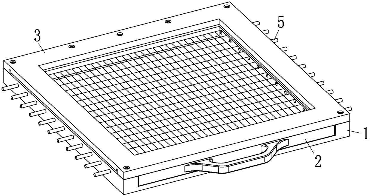
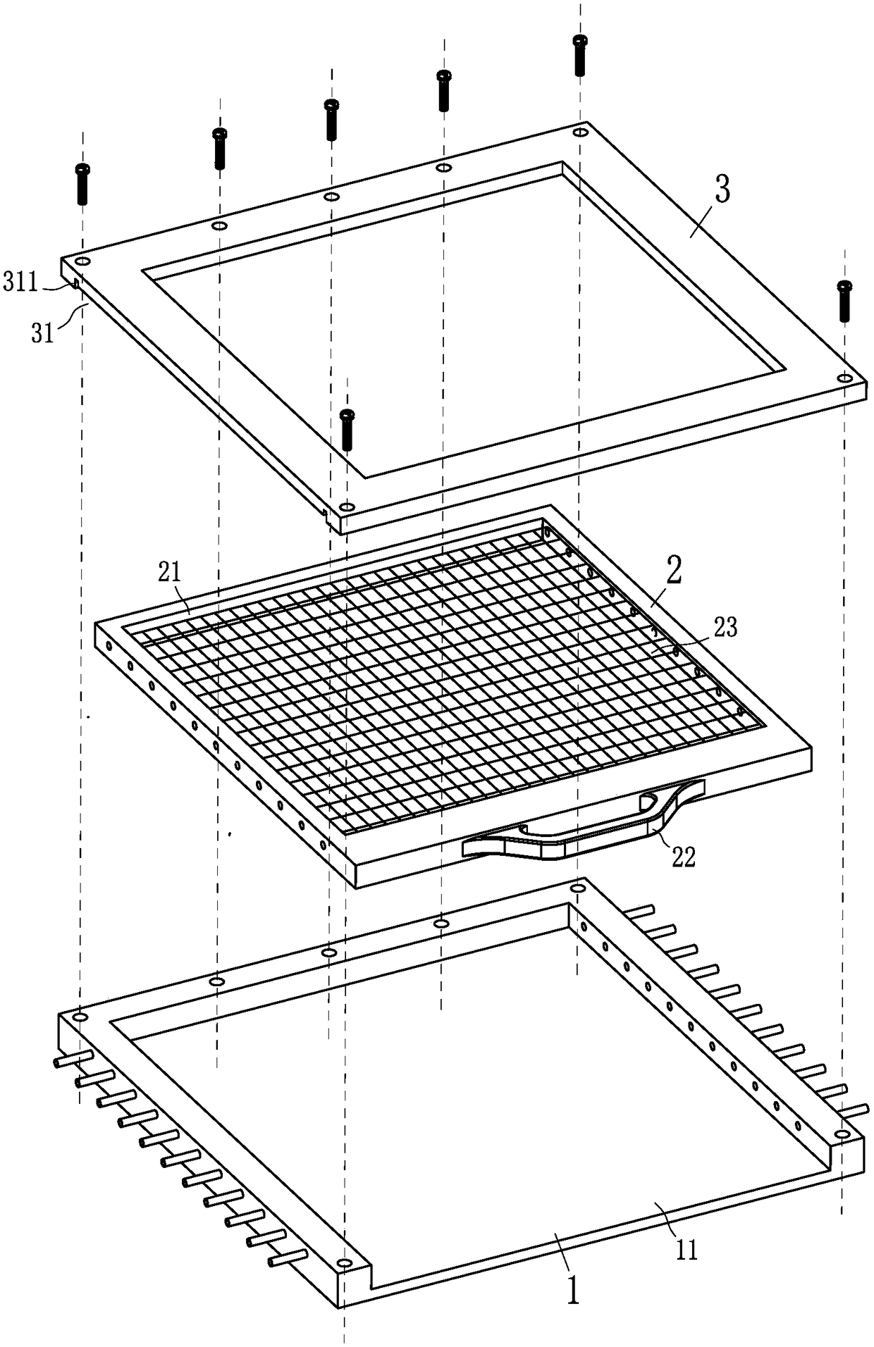
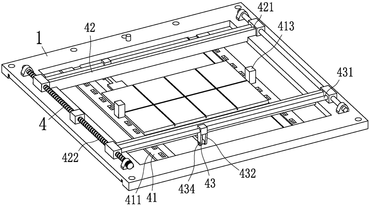
[0034] like figure 1 and image 3 As shown in the figure, a fixture for a circuit board gong and triggering machine according to the present invention includes a bottom tool 1, a middle tool 2, an upper tool 3, a clamping unit 4 and a dust suction pipe 5; the bottom tool 1, the middle tool 2 and the upper tool 3 are both flat cube frame structures, the bottom tool 1 is connected with the cylinder of the circuit board gong trigger; the middle tool 2 is slidably nested in the bottom tool 1, and is used for receiving gongs The powder in the board process and the finished circuit board at the end of the gong board; the upper tool 3 is installed on the bottom tool 1 and is located at the upper end of the bottom tool 1 and the middle tool 2; the clamping u...


PUM


Abstract

The invention belongs to the field of circuit board cutting machines, and specifically relates to a circuit board cutting machine fixture. The circuit board cutting machine fixture comprises a bottom fixture, a middle fixture, an upper fixture, a clamping unit and a dust collection pipe; the bottom fixture is connected with a cylinder of a circuit board routing machine; the middle fixture is embedded in the bottom fixture in a sliding manner and is used for receiving powder generated in a board cutting process and a finished product circuit board after the board cutting operation is finished; the upper fixture is installed on the bottom fixture and is located at the upper ends of the bottom fixture and the middle fixture; the clamping unit is installed on the bottom fixture and is used for clamping the circuit board to be cut and automatically dropping the product circuit board into the middle fixture after the board cutting operation is finished; and the dust collection pipe is installed on the bottom fixture and is used for absorbing and recycling the powder in the middle fixture. The circuit board cutting machine fixture provided by the invention can be applicable to automatic board cutting of circuit boards with different specifications, no pin hole needs to be formed in the bottom plate of the circuit board cutting machine just like the traditional circuit board cutting machine, and the product circuit board is convenient to manually take up after the board cutting operation is finished.

Description

technical field [0001] The present invention relates to the field of circuit board gongs, in particular to a clamp for circuit board gongs. Background technique [0002] In the production process of circuit boards, for boards with relatively small delivery units but a large number of delivery quantities, in order to reduce costs and improve production efficiency, multiple units are usually assembled together according to a certain geometry (units and There is a distance of 1-2MM between units), forming a large rectangular work board for production. When the production of the circuit board is completed, the CNC gong bed is used to carry out the gong along the interval area between the units before delivery to separate the individual delivery units on the board. The existing gong board method is: drilling positioning holes on the bottom plate of the gong machine (at least 2 positioning holes for each shipping unit), then punching pins, and fixing the circuit board on the bott...

Claims


Application Information

Patent Timeline
Patent Type & Authority Patents(China)
IPC IPC(8): H05K3/00
CPCH05K3/0044H05K2203/0139H05K2203/15
Inventor 林春芳
Owner 福建必冠芯电科技股份有限公司
Learn More