Wig

A wig and artificial hair technology, applied in the field of wigs, can solve the problems that cannot be eliminated

Inactive Publication Date: 2017-05-10
ADERANS CO LTD
View PDF8 Cites 2 Cited by
  • Summary
  • Abstract
  • Description
  • Claims
  • Application Information

AI Technical Summary

Problems solved by technology

[0011] Such a tunnel phenomenon can only be achieved by implanting artificial hair with a bending rigidity value lower than that of the original head hair on the periphery of the wig (Patent Document 1), or by implanting artificial hair with a thinner hair diameter on the periphery of the wig (Patent Document 2) cannot be eliminated

Method used


Image

  • Wig
  • Wig
  • Wig

Examples


Embodiment Construction

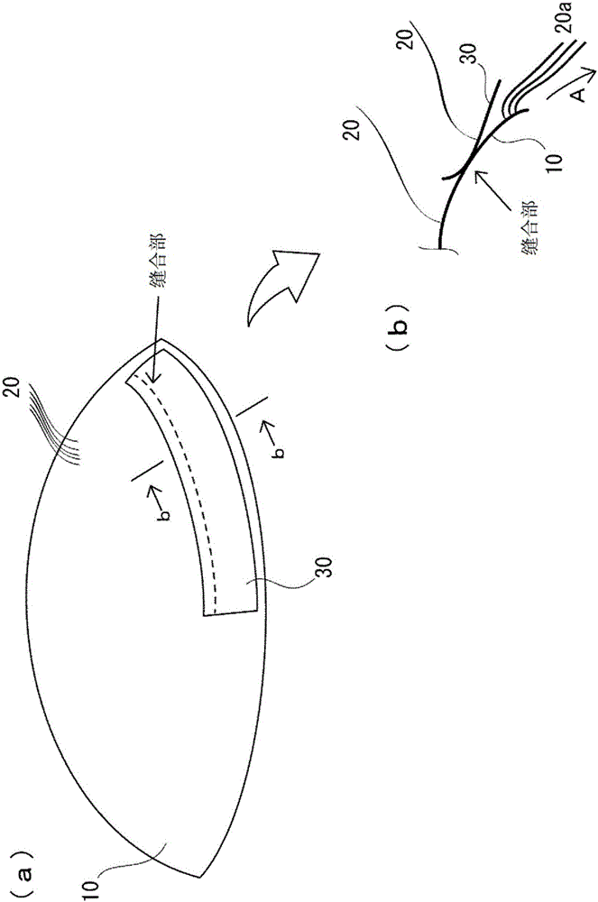
[0022] Embodiments of the present invention will be described below with reference to the drawings. figure 1 It is a perspective view explaining the wig which concerns on one Embodiment of this invention. The wig is formed by implanting artificial hair 20 (natural hair or artificial hair) on a wig base 10 worn on the wearer's head. figure 1 In , only a part of the artificial hair 20 is drawn, but in fact, the artificial hair 20 is implanted on the entire wig 10 .

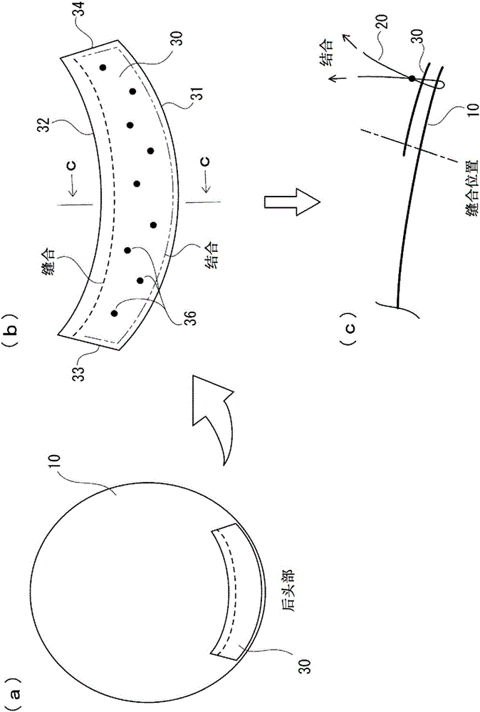
[0023] (wig base 10 and pressing piece 30)

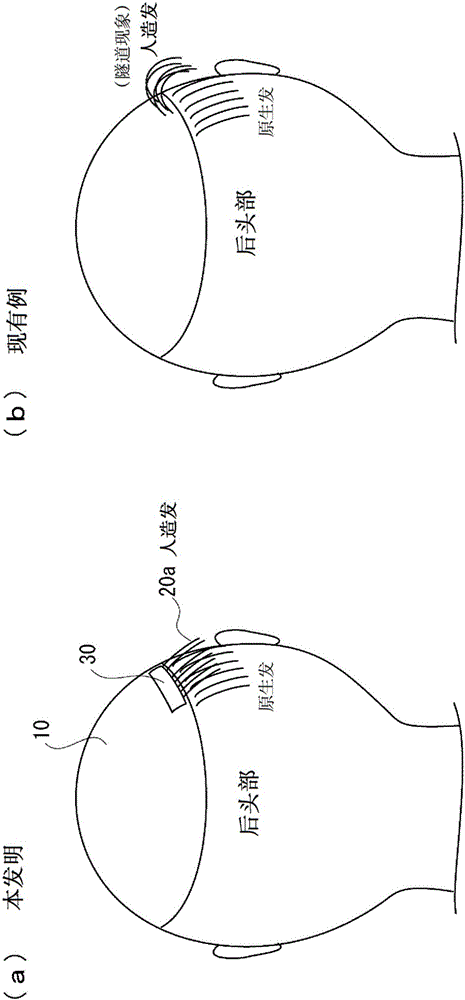
[0024] At least a part of the peripheral area of ​​the wig base 10 is fixed with a pressure member 30 having a predetermined width. figure 1 (b) means figure 1 Sectional view of line bb in (a). As shown in this cross-sectional view, the pressing member 30 extends so as to cover the roots of the artificial hair 20a implanted around the wig. Afterwards, by fixing the entire pressing member 30 on the wig base 10 (details will be described later), the artificial hair...


PUM


Abstract

The invention discloses a wig. In at least a portion of the peripheral region of a wig base (10) that is fitted to the head of a wearer, a pressing member (30) having a prescribed width is fixed to the wig base (10) so as to cover the root of an imitation hair (20a) that has been set in the wig base (10). The imitation hair (20a) in the wig periphery, said hair being held down by the pressing member (30), protrudes outwardly along the extension direction of the wig base (10), and this direction is close to the extension direction of the user's own hair which is remaining on the head. Consequently, a tunnel phenomenon can be prevented, and affinity between imitation hair (20a) and the user's own hair is improved.

Description

technical field [0001] The invention relates to a wig formed by implanting artificial hair on a wig base. Background technique [0002] There are partial wigs and full head wigs in wigs. Partial wigs are used to cover only the bald part of the head or to cover the original gray hair on the head, and to increase the volume of the hair on the parting line. Full head wigs, on the other hand, literally cover the entire head of the wearer. [0003] In general, for wigs, it is required that it is difficult for others to see that the wig is worn (camouflage effect). In this regard, a full head wig does not affect the state of the original hair on the head, but a partial wig has a dividing line between the periphery of the wig and the original hair on the head, so it takes effort to improve the camouflage effect. [0004] If the artificial hair implanted in the wig is not in harmony with the original hair on the head near the boundary line between the periphery of the wig and the...

Claims


Application Information

Patent Timeline
Patent Type & Authority Applications(China)
IPC IPC(8): A41G3/00
CPCA41G5/002A41G3/005
Inventor 川崎睦
Owner ADERANS CO LTD
Why Eureka
Try Eureka