Machine room-less elevator
一种无机房电梯、曳引机的技术,应用在升降机、运输和包装等方向,能够解决成本高、轨道比例大、轨道尺寸变大等问题,达到设备成本降低、减小轨道尺寸的效果
- Summary
- Abstract
- Description
- Claims
- Application Information
AI Technical Summary
Problems solved by technology
Method used
Image

Examples
Embodiment approach 1
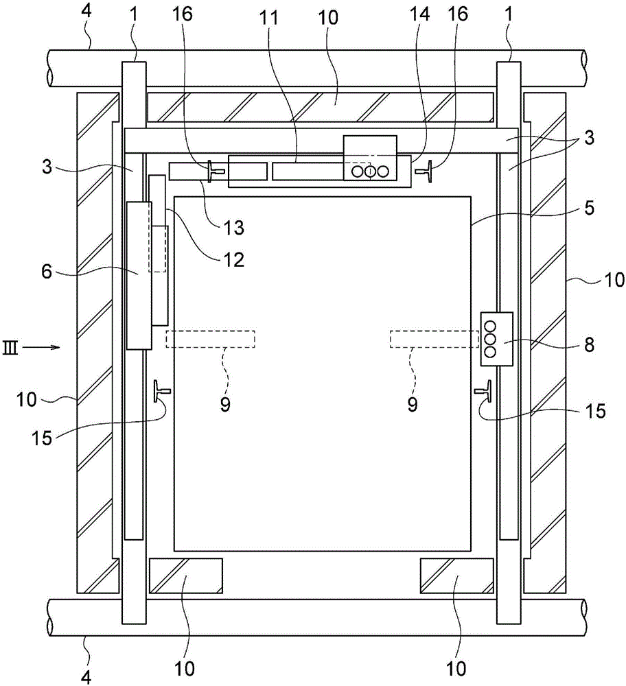
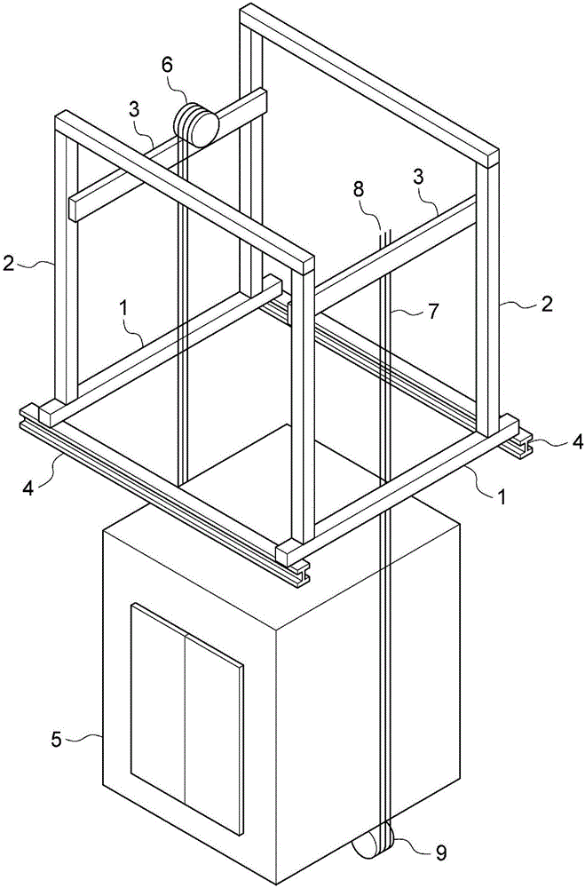
[0022] figure 1 It is a top view of the machine-room-less elevator of Embodiment 1, figure 2 It is a diagram schematically showing the relationship between the car and the beam of the machine-room-less elevator according to the first embodiment. image 3 is shown from figure 1 A diagram of the state of the main structural elements of the machine room-less elevator observed in the transverse direction (arrow III).
[0023] The elevator has a car 5 moving up and down in a shaft defined by a shaft wall 10 , a counterweight 14 , a pair of left and right car guide rails 15 , and a pair of left and right counterweight guide rails 16 . The left and right pair of car guide rails 15 and the left and right pair of reusable guide rails 16 respectively extend up and down in the hoistway. In the first embodiment of the counterweight rear type, the counterweight 14 is arranged behind the car 5 (on the opposite side of the landing) in plan view.
[0024] The car 5 is disposed between a ...
Embodiment approach 2
[0036] Next, based on Figure 4 Embodiment 2 of the present invention will be described. Figure 4 It is about this embodiment 2 and image 3 Figures in the same way. In addition, this Embodiment 2 is the same as the said Embodiment 1 except the part demonstrated below.
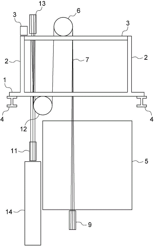
[0037] In Embodiment 2, the arrangement of the hoisting machine and the car-side return sheave in the configuration of Embodiment 1 is replaced. That is, the hoisting machine 6 in Embodiment 2 is installed on the first supporting beam portion 1 , and the car-side return sheave 12 is installed on one beam member of the third supporting beam portion 3 .
[0038] Also in the second embodiment configured in this way, the same advantages as those in the first embodiment described above are obtained. Moreover, in this Embodiment 2, compared with the case where a traction machine is installed in the 3rd support beam part, there exists an advantage that the maintenance space of a traction machine can be ensured e...
Embodiment approach 3
[0040] Next, based on Figure 5 and Figure 6 Embodiment 3 of the present invention will be described. Figure 5 and Figure 6 Respectively about this Embodiment 3 and figure 1 and image 3 Figures in the same way. In addition, this Embodiment 3 is the same as the said Embodiment 1 except the part demonstrated below.
[0041] In Embodiment 1 of the side-positioned counterweight type, the counterweight 14 is arranged on the side of the car 5 in plan view, and the return sheave is not required. Above the uppermost floor beam 4 are provided a first support beam portion 101 , a second support beam portion 102 , and a third support beam portion 103 .
[0042] The first support beam portion 101 includes a pair of beam members extending horizontally and on the same straight line. The first support beam portion 101 does not extend continuously in a manner spanning between the pair of beam members of the uppermost floor beam 4 , but the pair of beam members of the first support ...
PUM
 Abstract
Description
Claims
Application Information
 - Generate Ideas
- Intellectual Property
- Life Sciences
- Materials
- Tech Scout
- Unparalleled Data Quality
- Higher Quality Content
- 60% Fewer Hallucinations
Browse by: Latest US Patents, China's latest patents, Technical Efficacy Thesaurus, Application Domain, Technology Topic, Popular Technical Reports.
© 2025 PatSnap. All rights reserved.Legal|Privacy policy|Modern Slavery Act Transparency Statement|Sitemap|About US| Contact US: help@patsnap.com