Vehicle brake actuator

A vehicle braking and actuator technology, applied in the direction of brakes, brake actuators, transmissions, etc., can solve the problem of affecting the reliability of braking, harmful to the safety of vehicle passengers, and unsatisfactory application of electromechanical brake actuators And other issues

Inactive Publication Date: 2017-05-10
CHASSIS BRAKES INT BV
View PDF6 Cites 0 Cited by
  • Summary
  • Abstract
  • Description
  • Claims
  • Application Information

AI Technical Summary

Problems solved by technology

It is understood that reversibility constitutes a serious drawback since unintentional movement of the screw or housing according to linear motion could affect the reliability of the braking and thus be detrimental to the safety of the vehicle occupants
[0006] In addition, the application of electromechanical brake actuators using ball screws is not satisfactory in view of cost

Method used


Image

  • Vehicle brake actuator
  • Vehicle brake actuator
  • Vehicle brake actuator

Examples


Embodiment Construction

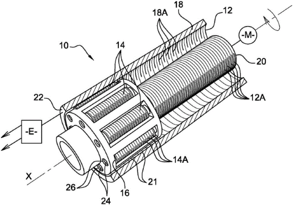
[0037] refer to figure 1 , in the brake actuator according to the present invention, the reducer 10 includes an internal screw 12 , a roller 14 arranged around the screw, a frame 16 for carrying the roller, and a casing 18 .

[0038] The screw 12 has three threads 12A facing the same first direction. One end 20 of the screw 12 is arranged to be fixed rigidly to a rotary drive, such as the motor M of the actuator. Thus, the retarder is provided to be electrically controlled. The other end of the screw comprises a smooth and hollow free edge.

[0039] The roller 14 is threaded and has a longitudinal axis parallel to the axis X of the screw. These rollers each have a single flight 14A that directly engages the flight 12A of the screw. The flight 14A of each roller 14 faces in the opposite direction to the flight 12A of the screw 12 .

[0040] The frame 16 for carrying the rollers 14 has a cylindrical shape coaxial with the screw 12 and extends over a small part of the screw ...


PUM


Abstract

The vehicle brake actuator (10) comprises: a screw (12), a tapped internal casing (18) in mesh with the screw (12) by means of an irreversible connection, an electric motor (M) commanding a movement of the screw (12) with respect to the internal casing (18) or of the internal casing with respect to the screw so that this movement actuates a brake element (E), threaded internal rollers (14), the internal rollers (14) each being in mesh firstly with the screw (12) and secondly with the internal casing (18) by means of at least one thread (14A), a tapped external casing (30), and external rollers (28) each in mesh firstly with the internal casing (18) and secondly with the external casing (30), the external rollers (28) being provided with at least one thread (28A) of opposite hand to a thread (18A) of the internal casing (18) of the same hand as a thread (30A) of the external casing (30).

Description

technical field [0001] The invention relates to the field of brake actuators for vehicles, and more particularly to the field of brake actuators of the electromechanical type. Background technique [0002] Vehicles using hydraulic braking devices are known. Such devices use hydraulic actuators, in particular comprising pistons capable of pressing the brake pads against a disc rigidly connected to the wheel. [0003] However, since a few years ago electromechanical brakes actuated electrically rather than hydraulically have been available. These braking devices are provided with an electromechanical actuator, which in particular has the advantage of not only reducing the manufacturing costs of the vehicle but also reducing the maintenance costs of the vehicle by eliminating the maintenance of the hydraulic circuit. [0004] In particular, an electromechanical brake device is known from application EP-1 359 338, which uses an electromechanical brake actuator provided with ba...

Claims


Application Information

Patent Timeline
Patent Type & Authority Applications(China)
IPC IPC(8): F16D65/14F16D121/24F16D121/14F16D125/40
CPCF16D65/14F16D2121/14F16D2121/24F16D2125/40B60T13/741F16D65/18F16D2125/405F16D2125/48F16H25/2252F16D2125/50
Inventor 蒂埃里·帕斯奎特菲利普·特雷格
Owner CHASSIS BRAKES INT BV
Why Eureka
Try Eureka