Automatic termite monitoring luring device

An automatic monitoring and termite technology, which is applied to the device for catching or killing insects, application, animal husbandry, etc. It can solve the problems of easy shaking, affecting use, and inability to monitor termites, so as to avoid shaking, good use effect, and save manpower. Material effect

Inactive Publication Date: 2017-05-17
陈福昌
View PDF5 Cites 2 Cited by
  • Summary
  • Abstract
  • Description
  • Claims
  • Application Information

AI Technical Summary

Problems solved by technology

[0002] Termites are very harmful to house construction, especially the damage to brick and wood structure buildings. When the supporting structure of the house is damaged by termites or its bearing points are damaged, the house often collapses suddenly. The termites have strong diffusion and large groups , Rapid destruction, can cause huge losses in a short period of time
In order to prevent problems before they happen, generally when building a building, the termite colony on the construction site will be mass-killed. The means of killing include killing drugs, etc. Hidden in the ground or inside the wooden structure, if the medicine is sprayed on a large area, it will not only increase the cost of killing termites, but also cause environmental pollution. Therefore, there is a termite luring monitoring device in the prior art, which is placed in a predetermined area. device, the monitoring device includes a casing, the outer wall of the casing is provided with holes for termites to enter and exit, the luring strips for attracting termites are placed in the casing, and then the monitoring device is buried in the ground of the construction site, and the monitoring device is taken out after a few days, the casing is opened, and taken out If there are traces of termite gnawing or a certain amount of termites inside, take out the lure strip and replace it with a medicine roll containing termite-killing drugs and substances that can attract termites, that is, the Termites are exterminated at the site. Since the low-cost and environmentally friendly lure strips are used to monitor the underground of the construction site, the use of high-cost and environmentally polluting drugs is reduced. This monitoring device is a technology worth promoting. The problem that this monitoring device exists is: because the construction site needs to bury the monitoring device according to a certain density, that is to say, on a construction site, the distribution amount of its monitoring device may be very large, and the monitoring device is buried in the ground for a period of time. After that, it is necessary to open the casing and take out the attracting strips for observation to determine whether there are termites in the area. The process of taking out the attracting strips for judgment is relatively cumbersome, and the number of monitoring devices will also make the judgment process more difficult At the same time, the breakage of the lure bar may cause the inner space of the casing to be blocked, resulting in the inability to accommodate the medicine roll inside the casing, which affects its use and needs to be improved urgently
There are still some deficiencies in the use of this technical solution: the external rainwater is easy to soak the axis bar and the lure bar through the through hole, which affects the use; because the inner side is directly put into the shell, there is no limit structure, when installing and disassembling , the inner side is easy to shake, and the through holes on the outer cover and inner cover are dislocated, which affects the use; due to the limitation of the structure itself, this technical solution cannot monitor termites in deeper areas; Improve

Method used


Image

  • Automatic termite monitoring luring device

Examples


Embodiment Construction

[0017] It should be noted that, in the case of no conflict, the embodiments in the present application and the features in the embodiments can be combined with each other; the present invention will be described in detail below with reference to the accompanying drawings and in combination with the embodiments.

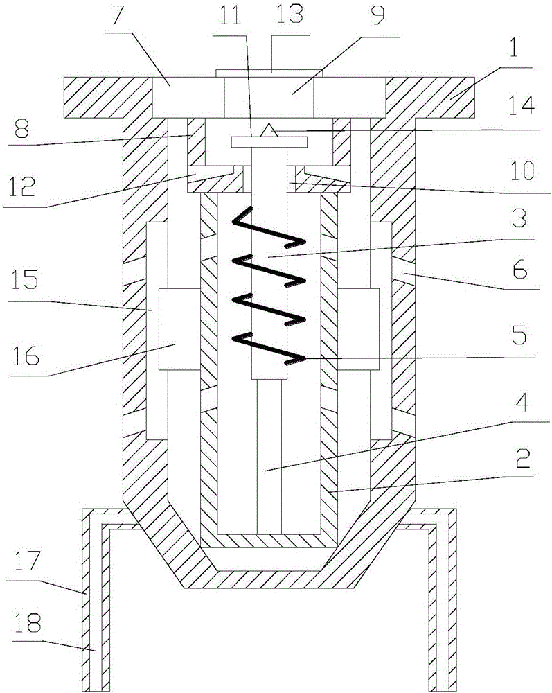
[0018] refer to figure 1 :

[0019] A termite automatic monitoring and luring device proposed by the present invention includes an outer shell 1, an inner shell 2, an axial bar 3, an attracting bar 4, and a spring 5, and the side walls of the outer shell 1 and the inner shell 2 are provided with holes for termites to enter 6. The outer shell 1 is equipped with a detachable outer cover 7, the inner shell 2 is equipped with an inner cover 8, and the inner shell 2 and the inner cover 8 are placed in the outer shell 1; the axis bar 3, the lure bar 4, and the spring 5 are placed in the inner shell 2 within.

[0020] The outer cover 7 is provided with a first through hole...


PUM


Abstract

The invention discloses an automatic termite monitoring luring device. The automatic termite monitoring luring device comprises an outer shell, an inner shell, an axis strip, a luring strip and a spring, gaps for the termite to enter are arranged on the side walls of both the outer shell and the inner shell, the outer shell is provided with a detachable outer lid, the inner shell is provided with an inner lid, and the inner shell and the inner lid are placed in the outer shell; the axis strip, the luring strip and the spring are placed in the inner shell; a first through hole is formed in the outer lid; a second through hole is formed in the inner lid, the axial line of the second through hole coincides with the axial line of the first through hole, and the diameter of the second through hole is smaller than that of the first through hole. In the termite automatic monitoring luring device, by arranging a convex edge on a first end of the axis strip, sundries of rainwater and the like are effectively prevented from entering the inner shell; by adding a limiting groove, a mobile piece and a positioning rod, the outer shell and the inner shell can be effectively fixed, the outer shell and the inner shell are effectively prevented from shaking, and the using effect is better.

Description

technical field [0001] The invention relates to the technical field of termite monitoring equipment, in particular to an automatic termite monitoring and luring device. Background technique [0002] Termites are very harmful to house construction, especially the damage to brick and wood structure buildings. When the supporting structure of the house is damaged by termites or its bearing points are damaged, the house often collapses suddenly. The termites have strong diffusion and large groups , The damage is rapid, and it can cause huge losses in a short period of time. In order to prevent problems before they happen, generally when building a building, the termite colony on the construction site will be mass-killed. The means of killing include killing drugs, etc. Hidden in the ground or inside the wooden structure, if the medicine is sprayed on a large area, it will not only increase the cost of killing termites, but also cause environmental pollution. Therefore, there is...

Claims


Application Information

Patent Timeline
Patent Type & Authority Applications(China)
IPC IPC(8): A01M1/02
CPCA01M1/026
Inventor 陈福昌
Owner 陈福昌
Why Eureka
Try Eureka