Eureka AIR delivers breakthrough ideas for toughest innovation challenges, trusted by R&D personnel around the world.

Positioning mechanism

A technology of positioning mechanism and positioning plate, which is applied in the field of vehicles, can solve the problems such as the deviation of the positioning pin shaft and the inability to ensure that the positioning pin shaft and the pipe casing are completely coaxial, and achieve the effect of improving accuracy

Inactive Publication Date: 2017-05-17
BAIC MOTOR CORP LTD
View PDF6 Cites 9 Cited by
  • Summary
  • Abstract
  • Description
  • Claims
  • Application Information

AI Technical Summary

Problems solved by technology

At present, most of the positioning pins of welding fixtures are designed in such a way that the axis of the positioning pin goes down, and the hole of the pipe casing goes up, so as to realize the welding positioning. This kind of positioning cannot ensure that the axis of the positioning pin is completely coaxial with the casing of the pipe, and there is an improvement. space

Method used


Image

  • Positioning mechanism
  • Positioning mechanism
  • Positioning mechanism

Examples


Embodiment Construction

[0023] Embodiments of the present invention are described in detail below, examples of which are shown in the drawings, wherein the same or similar reference numerals designate the same or similar elements or elements having the same or similar functions throughout. The embodiments described below by referring to the figures are exemplary and are intended to explain the present invention and should not be construed as limiting the present invention.

[0024] In describing the present invention, it should be understood that the terms "center", "longitudinal", "transverse", "length", "width", "thickness", "upper", "lower", "front", " The orientation or positional relationship indicated by "rear", "left", "right", "vertical", "horizontal", "top", "bottom", "inner" and "outer" are based on the orientation or position shown in the drawings The positional relationship is only for the convenience of describing the present invention and simplifying the description, but does not indica...


PUM


Abstract

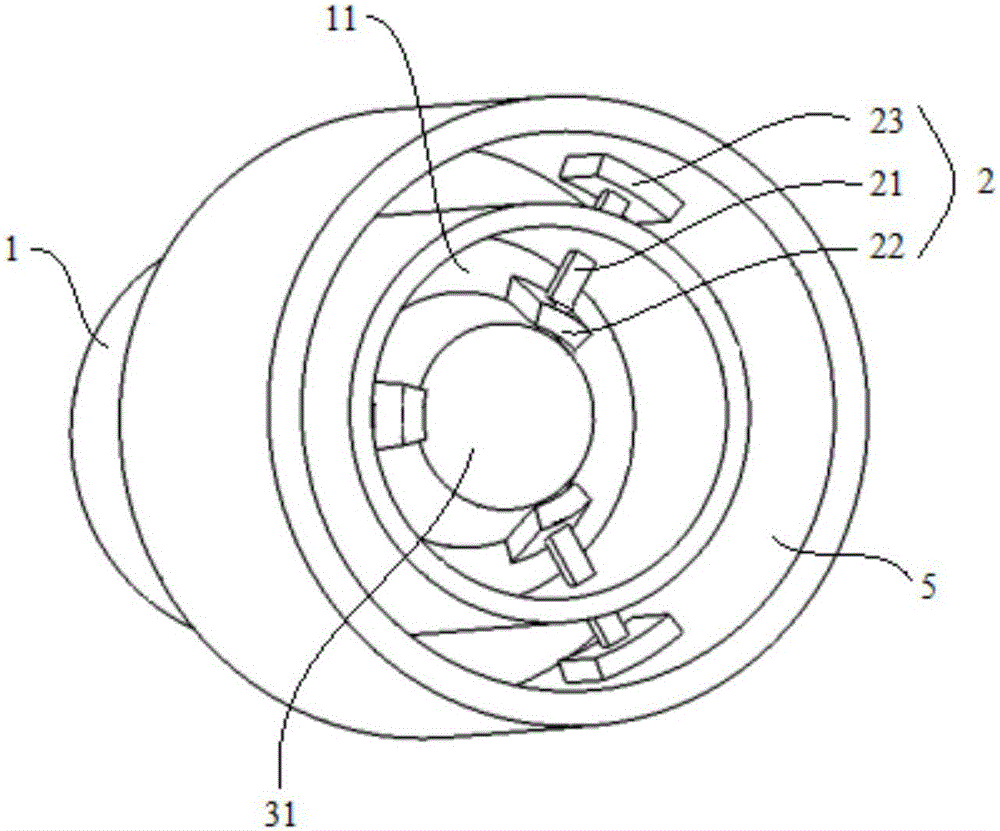
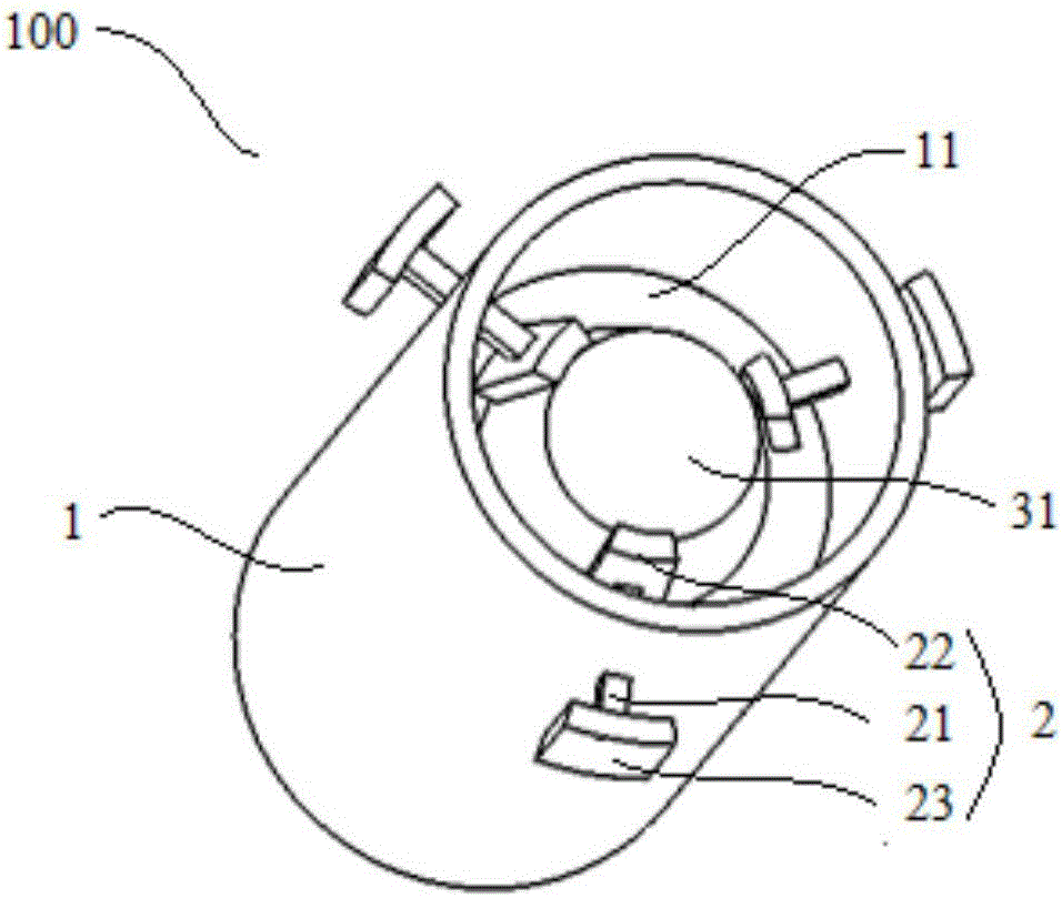
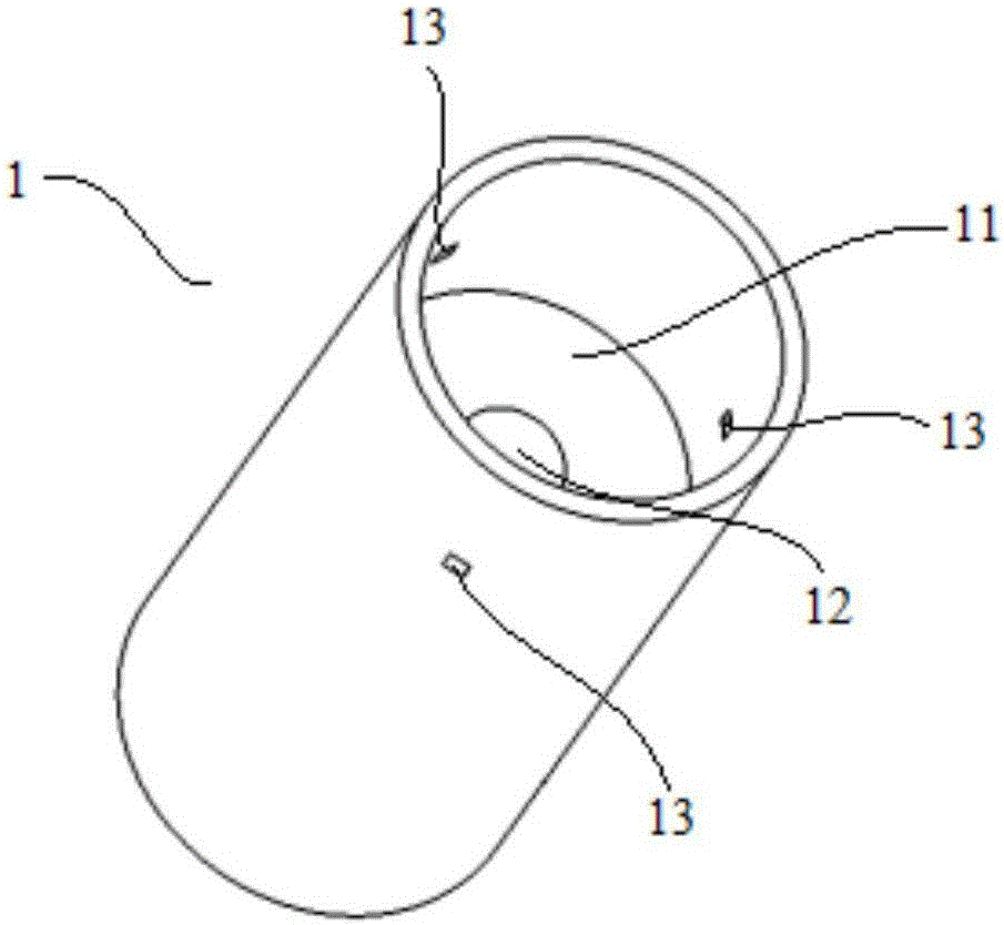
The invention discloses a positioning mechanism which comprises a dowel pin base, a plurality of positioning cores and a positioning shaft, wherein each positioning core comprises a connecting rod, an inner end positioning plate and an outer end positioning plate, the connecting rod is arranged on the peripheral wall of the dowel pin base in a penetrating mode, the inner end of the connecting rod is equipped with the inner end positioning plate, the outer end of the connecting rod is equipped with the outer end positioning plate, and the connecting rod can move in the radial direction of the peripheral wall relative to the peripheral wall; the positioning shaft is coaxially arranged inside the dowel pin base; the positioning shaft is provided with a positioning tapered surface which is suitable for fitting with the inner end positioning plate, and the positioning shaft can move in the axial direction of the positioning shaft relative to the dowel pin base, so that the positioning cores are driven through the tapered surface to synchronously move in the radial direction. The positioning mechanism disclosed by the invention is simple in structure, is convenient to dismount, and is beneficial for improving precision of a part dimension.

Description

technical field [0001] The invention relates to the technical field of vehicles, in particular to a positioning mechanism. Background technique [0002] Locating pins are common fixtures in the process of welding, processing and manufacturing auto parts. The installation points of subframes, swing arms, rods and other components in the suspension system are usually designed as pipe casing structures. The position of the geometric center of the pipes requires strict. At present, most of the positioning pins of welding fixtures are designed in such a way that the axis of the positioning pin goes down, and the hole of the pipe casing goes up, so as to realize the welding positioning. This kind of positioning cannot ensure that the axis of the positioning pin is completely coaxial with the casing of the pipe, and there is an improvement. space. Contents of the invention [0003] The present invention aims to solve one of the above-mentioned technical problems in the prior ar...

Claims


Application Information

Patent Timeline
Patent Type & Authority Applications(China)
IPC IPC(8): B23K37/053
CPCB23K37/0531
Inventor 侯建勇连甲虎彭锋
Owner BAIC MOTOR CORP LTD
Why Eureka
Eureka Blog
Learn More