Frame automatic film pasting device and film pasting method thereof

A film sticking device and frame technology, applied in packaging and other directions, can solve the problems of unable to stick film on products with corners, large manpower demand, complex structure, etc., and achieve the effect of simple structure, good applicability, and simple operation

Inactive Publication Date: 2017-05-17
HEFEI BYAT AUTOMATIC TECH CO LTD
View PDF8 Cites 8 Cited by
  • Summary
  • Abstract
  • Description
  • Claims
  • Application Information

AI Technical Summary

Problems solved by technology

The film sticking methods commonly used in the prior art include: (1) artificial film sticking, which has low efficiency, poor effect, and large manpower demand; (2) uses automatic film sticking machines on the market to stick film, but the existing automatic Most of the film laminating machines have complex structures, and can only apply film to straight frames, and cannot apply film to products with corners, such as U-shaped frames, which have poor applicability

Method used


Image

  • Frame automatic film pasting device and film pasting method thereof
  • Frame automatic film pasting device and film pasting method thereof
  • Frame automatic film pasting device and film pasting method thereof

Examples


Embodiment 1

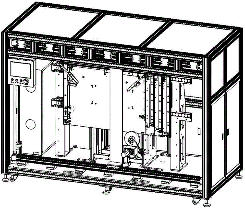
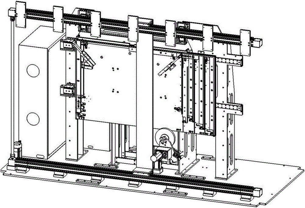
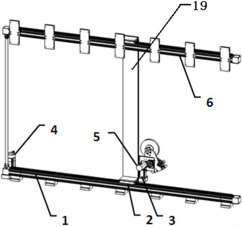
[0061] Such as Figure 1-2 As shown, a frame automatic film sticking device includes a frame automatic positioning device, a film sticking mechanism and an automatic film covering mechanism; the frame automatic positioning device fixes the frame to be filmed on the jig plate; the film sticking mechanism is used to place the protective film Paste on the outer walls around the frame to be filmed, and the film sticking mechanism includes a first horizontal linear module 1, a second horizontal linear module 6, a vertical linear module 19, a film assembly, a first motor 4, and a second motor 3 and the third motor 5; the first horizontal linear module 1 is parallel to the second horizontal linear module 6, and the second horizontal linear module 6 is located above the first horizontal linear module 1; the vertical linear module The two ends of 19 are respectively connected with the first horizontal linear module 1 and the second horizontal linear module 6; the first motor 4 is arran...

Embodiment 2

[0072] The difference between this embodiment and Embodiment 1 is:

[0073] Such as Figure 12-17 As shown, the laminating mechanism includes a laminating frame and a displacement assembly, and the laminating frame is provided with an upper laminating cylinder 203, a left laminating cylinder 201, and a right laminating cylinder 204; the upper laminating cylinder 203 , the left laminating cylinder 201 and the right laminating cylinder 204 are respectively provided with a first flattening part 216, a second flattening part 202 and a third flattening part 217; The bit assembly includes: a fourth motor 209, a gear 211, a rack 212, a jig connecting plate 207, and a first connecting plate 214. The output shaft of the fourth motor 209 is connected to the gear 211, and the gear 211 meshes with the rack 212. The two ends of the fixture connection plate 207 are connected with a fixture fixing plate 208, and the fixture connection plate 207 is also connected with the rack 212; the first...

Embodiment 3

[0081] The difference between this embodiment and embodiment one and embodiment two is:

[0082] Such as Figure 18-22 As shown, the frame automatic positioning device includes a fixture plate 107, a left positioning cylinder 104, an upper positioning cylinder 108, a right positioning cylinder, a left corner cylinder 102, an upper corner cylinder 106, a right corner cylinder 109 and an inner top cylinder 103; the left positioning cylinder 104, the upper positioning cylinder 108, and the right positioning cylinder are respectively arranged on the left outer side, the upper outer side, and the right outer side of the fixture plate 107, and the left positioning cylinder 104, the upper positioning cylinder 108, and the piston on the right positioning cylinder The direction of motion of the rod is all perpendicular to the corresponding sidewall on the fixture plate 107; the left corner cylinder 102, the upper corner cylinder 106, and the right corner cylinder 109 are respectively a...


PUM


Abstract

The invention discloses a frame automatic film pasting device and a film pasting method thereof. The frame automatic film pasting device comprises a frame automatic locating device, a film pasting mechanism and a film coating mechanism. The frame automatic locating device fixes a frame to be subjected to film pasting to a jig plate. The film pasting mechanism is used for pasting a protective film to the peripheral outer side wall of the frame to be subjected to film pasting. The film coating mechanism pastes the protective film exposed on the peripheral outer side wall of the frame to be subjected to film pasting to the position, uncoated with a film, of the frame to be subjected to film pasting. The frame automatic film pasting device is simple in structure and easy to operate, film pasting can be carried out on non-plane products, that is, film pasting can be carried out on articles with corners, and applicability is good.

Description

technical field [0001] The invention specifically relates to a frame automatic film sticking device and a film sticking method thereof. Background technique [0002] In order to avoid problems such as scratches during transportation, it is usually necessary to stick a protective film on the surface of the product after the product is produced and before packaging. The film sticking methods commonly used in the prior art include: (1) artificial film sticking, which has low efficiency, poor effect, and large manpower demand; (2) uses automatic film sticking machines on the market to stick film, but the existing automatic Most of the film laminating machines have complex structures, and can only apply film to straight frames, and cannot apply film to products with corners, such as U-shaped frames, which have poor applicability. Contents of the invention [0003] In view of the above problems, the present invention proposes an automatic frame film sticking device and a film s...

Claims


Application Information

Patent Timeline
Patent Type & Authority Applications(China)
IPC IPC(8): B65B33/02
CPCB65B33/02
Inventor 李静远韩宝清
Owner HEFEI BYAT AUTOMATIC TECH CO LTD
Why Eureka
Try Eureka