Acoustic emission test sensor installation and clamping device and test piece installation method

A sensor and acoustic emission technology, applied in the field of rock mechanics experiments, can solve the problems of inaccurate positioning, inconvenient operation, time-consuming and laborious, etc., and achieve the effect of convenient operation and improved positioning accuracy

Active Publication Date: 2019-11-08
UNIV OF SCI & TECH BEIJING
View PDF7 Cites 0 Cited by
  • Summary
  • Abstract
  • Description
  • Claims
  • Application Information

AI Technical Summary

Problems solved by technology

[0003] In order to overcome the problems of inaccurate positioning, easy sliding of the sensor, inconvenient operation, time-consuming and labor-intensive problems in the installation process of the acoustic emission test sensor, the present invention provides an acoustic emission test sensor installation and clamping device and a test piece installation method. Positioning and clamping to complete the fixation of the sensor

Method used


Image

  • Acoustic emission test sensor installation and clamping device and test piece installation method
  • Acoustic emission test sensor installation and clamping device and test piece installation method
  • Acoustic emission test sensor installation and clamping device and test piece installation method

Examples


Embodiment 1

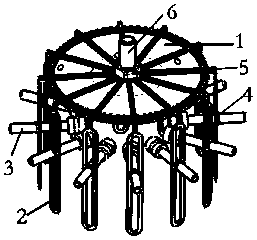
[0045] For the standard 50mm diameter, 100mm circumference cylindrical specimen for the acoustic emission test, as required Figure 9In the installation method shown, the test piece is first placed on a platform, and then the base is placed on the top of the test piece through the sinking groove, and then the fixed teeth of the return-shaped folding arm are clamped in the annular groove. The fixed arm of the shaped folding arm is stuck in the concave draw-in groove according to the equidistant, naturally downwards, then tightens the second nut along the central axis column to fix the curved folding arm with adjusted angle and spacing. Pass the threaded section of the grooved bolt out of the clamping opening, the groove end faces inward, the top surface of the sensor receiving the signal is coated with glue, and the other top surface is embedded in the groove, the grooved bolt is perpendicular to the space of the central axis column , adjust the distance in the vertical directi...

Embodiment 2

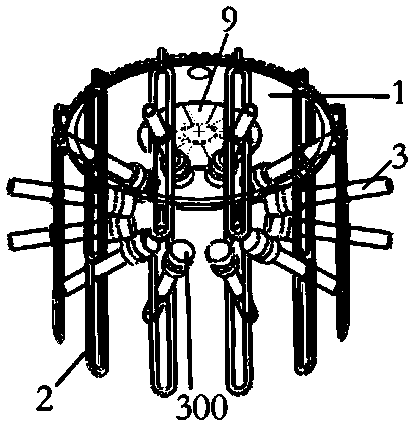
[0047] This embodiment tells about the installation method for the disc test piece that carries out splitting test acoustic emission detection, such as Figure 10 , Figure 11 shown. First place the test piece on a cylindrical platform with a similar diameter, then place the circular sinking groove of the base on the upper top surface of the test piece, and then clamp the fixed teeth of multiple return-shaped folding arms in the annular groove Among them, the fixed arm is stuck in the concave slot according to the equal distance, and the return-shaped clamping mouth is naturally downward, and then the second nut is tightened along the central axis column to fix the return-shaped folding arm with adjusted angle and spacing. Pass the threaded section of the grooved bolt out of the return-shaped clamping opening, the groove end faces inward, the top surface of the sensor receiving the signal is coated with glue, and the other top surface is embedded in the groove, the grooved bo...


PUM


Abstract

The invention provides an acoustic emission test sensor mounting and clamping device. The device comprises a disk-shaped pedestal, zigzag arms, groove bolts, first nuts and a second nut, a middle axlestanding column and an annular groove are fixed at the center of the upper end of the pedestal, a concave clamping groove is arranged at the edge of the upper end surface of the pedestal, and a sinkgroove for fixing a test piece is arranged on the lower end surface of the pedestal; every zigzag arm includes a fixing arm and a zigzag clamping opening, a fixing tooth is arranged at one end of thefixing arm, the other end is connected with the zigzag clamping opening, and the plurality of zigzag arms are fixed in a radial direction through the clamping connection between the fixing teeth and the annular groove, and are circumferentially fixed through the clamping connection between the fixing arms and the concave clamping groove; and a groove for accommodating a sensor is arranged at one end of every groove bolt, the other end of every groove bolt is a bolt segment, and the bolt segments outward pass through the zigzag clamping openings and then are screwed with the first nuts. The device has the advantages of improvement of the positioning precision of the sensor, no manual clamping, convenience in operation, avoiding of sliding of the sensor due to non-solidification of glue, andrealization of determination of the position of the sensor in a large range.

Description

technical field [0001] The invention relates to the field of rock mechanics experiments, in particular to an acoustic emission test sensor installation and clamping device and a test piece installation method. Background technique [0002] During the deformation process of rocks and metals, under the condition of compression and tension, when the stress does not exceed the previous maximum stress, there is no acoustic emission. Once the stress exceeds the maximum stress previously experienced by the material, the AE activity increases significantly. The acoustic emission activity has the characteristic of stress memory—that is, the stress on the material in the past can be measured through acoustic emission. This is called the Kaiser effect. When performing acoustic emission tests such as uniaxial compression and Brazilian wall cracks on standard rock specimens, the acoustic emission sensor used to detect acoustic emission events needs to be fixed on the test specimen with ...

Claims


Application Information

Patent Timeline
Patent Type & Authority Patents(China)
IPC IPC(8): G01N3/08
CPCG01N3/08G01N2203/0067
Inventor 高永涛王本鑫金爱兵孙金海
Owner UNIV OF SCI & TECH BEIJING
Why Eureka
Try Eureka