
Automatic frame locating device and method

A technology of automatic positioning and positioning method, applied in packaging, packaging machines, transportation and packaging, etc., can solve the problems of reducing production capacity, unable to provide help for border operation, and fast positioning action, so as to overcome inaccurate positioning and ensure accurate positioning. performance and efficiency, and the effect of reducing structural complexity

Inactive Publication Date: 2017-05-17
HEFEI BYAT AUTOMATIC TECH CO LTD
View PDF8 Cites 0 Cited by
  • Summary
  • Abstract
  • Description
  • Claims
  • Application Information

AI Technical Summary

Problems solved by technology

[0003] 1. It often only has a positioning function, and cannot provide help for subsequent operations on the frame;
[0004] 2. All the positioning components in the positioning device operate at the same time, which can easily cause the problem of low positioning accuracy;
[0005] 3. If the speed of the positioning action is too fast, it is easy to cause inaccurate frame positioning and poor positioning repeatability, thereby reducing production capacity and posing quality risks

Method used


Image

  • Automatic frame locating device and method
  • Automatic frame locating device and method
  • Automatic frame locating device and method

Examples


Embodiment 1

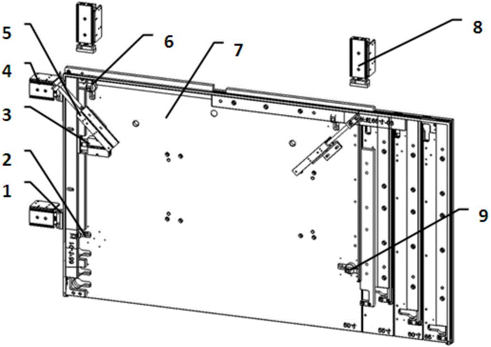
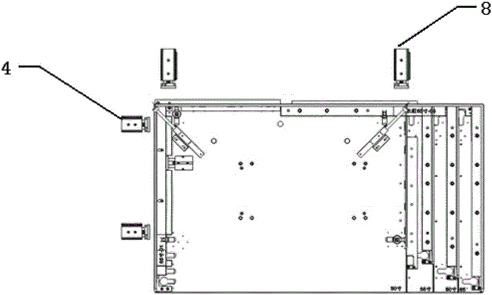
[0037] Such as Figure 1-5 As shown, a frame automatic positioning device includes a fixture plate 7, a left positioning cylinder 4, an upper positioning cylinder 8, a right positioning cylinder, a left corner cylinder 2, an upper corner cylinder 6, a right corner cylinder 9 and an inner top cylinder 3. The left positioning cylinder 4, the upper positioning cylinder 8, and the right positioning cylinder are respectively arranged on the left outer side, the upper outer side, and the right outer side of the jig plate 7, and the left positioning cylinder 4, the upper positioning cylinder 8, and the piston on the right positioning cylinder The direction of movement of the rods is all perpendicular to the corresponding side wall on the fixture plate 7; the left corner cylinder 2, the upper corner cylinder 6, and the right corner cylinder 9 are respectively arranged on the left inner side, the upper inner side and the right side of the fixture plate 7. Inner side, left corner cylind...

Embodiment 2

[0047] The difference between this embodiment and Embodiment 1 is that the frame automatic positioning device also includes a cutting part, and the cutting part includes a corner cutting cylinder 5 and a corner cutting knife 10 arranged on the piston rod of the corner cutting cylinder 5, and the corner cutting The cylinder 5 drives the corner cutting knife 10 to move towards the corner of the frame;

[0048]When the device of the present invention is used in a frame laminating machine, the corner cutting cylinder can be used to cut the film attached to the corner of the frame, so that when the frame is coated, no wrinkles will appear at the corner of the frame, greatly The application performance of the device of the present invention is improved.

Embodiment 3

[0050] A positioning method for an automatic frame positioning device, characterized in that it comprises the following steps:

[0051] Step 1. Put the frame to be positioned on the fixture plate 7;

[0052] Step 2, use the upper positioning cylinder 8 to withstand the upper outer side wall of the frame, and simultaneously use the left positioning cylinder 4 or the right positioning cylinder to withstand the left outer side wall or the right outer side wall of the frame;

[0053] Step 3, use the swing arm of the upper corner cylinder 6 to offset against the upper inner wall of the frame, and simultaneously use the swing arm of the left corner cylinder 2 or right corner cylinder 9 to offset the left inner wall or the right inner wall of the frame;

[0054] Step 4, use the inner top cylinder 3 to withstand the right inner wall or the left inner wall of the frame from the inside to the outside;

[0055] Step 5, use the right positioning cylinder or the left positioning cylinder ...


PUM


Abstract

The invention discloses an automatic frame locating device and method. The device comprises a jig plate, a left locating air cylinder, an upper locating air cylinder, a right locating air cylinder, a left corner air cylinder, an upper corner air cylinder, a right corner air cylinder and an inner jacking air cylinder. The left locating air cylinder, the upper locating air cylinder and the right locating air cylinder are arranged on the left outer side, the upper outer side and the right outer side of the jig plate respectively, and the movement direction of a piston rod on the left locating air cylinder, the movement direction of a piston rod on the upper locating air cylinder and the movement direction of a piston rod on the right locating air cylinder are all perpendicular to corresponding side walls on the jig plate. The left corner air cylinder, the upper corner air cylinder and the right corner air cylinder are arranged on the left inner side, the upper inner side and the right inner side of the jig plate respectively and all comprise an air cylinder body, a piston rod and a swing arm connected with the piston rod, and the rotary path lines of the swing arms are parallel to the front wall face and the rear wall face of the jig plate. The inner jacking air cylinder is arranged on the inner side of the jig plate, and the movement direction of a piston rod of the inner jacking air cylinder is perpendicular to the inner side wall of the jig plate. According to the automatic frame locating device and method, the stability of a frame can be guaranteed, and subsequent other operation on the frame can be carried out.

Description

technical field [0001] The invention belongs to the field of automation equipment, and in particular relates to a frame automatic positioning device and a positioning method. Background technique [0002] At present, in order to avoid defects such as scratches on the outer surface of the product due to bumps and other problems during the handling process of the produced frame, and to effectively prevent problems such as dust and pollution on the product surface, many manufacturers will choose to use the outside of the frame The protective film is pasted around, so the laminating machine has been widely used. Generally, an automatic frame positioning device is installed on the laminating machine to position the frame. However, the existing automatic frame positioning device on the laminating machine has the following defects: [0003] 1. It often only has a positioning function, and cannot provide help for subsequent operations on the frame; [0004] 2. All the positioning c...

Claims


Application Information

Patent Timeline
IPC IPC(8): B65B33/02B65B65/00
CPCB65B33/02B65B65/00
Inventor 李静远韩宝清
Owner HEFEI BYAT AUTOMATIC TECH CO LTD
Learn More