Hydraulic damper with rigidity adjusting function

A hydraulic damper and damper technology, applied in the field of hydraulic dampers, can solve problems such as solving difficulties

Active Publication Date: 2017-05-17
常州格林电力机械制造有限公司
View PDF6 Cites 10 Cited by
  • Summary
  • Abstract
  • Description
  • Claims
  • Application Information

AI Technical Summary

Problems solved by technology

In some special occasions, the rigidity requirements of the hydraulic damper are relatively strict. For the rigidity requirement of the hydraulic damper in one direction, we can achieve it by adjusting the structural stiffness of the hydraulic damper or replacing the working oil, but the hydraulic damper There are strict requirements on the stiffness in the tension and compression directions, so it is very difficult to solve

Method used


Image

  • Hydraulic damper with rigidity adjusting function
  • Hydraulic damper with rigidity adjusting function

Examples


Embodiment Construction

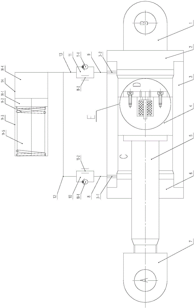
[0019] Such as figure 1 , figure 2 As shown, a hydraulic damper with stiffness adjustment function includes right pin head 1, right end cover 2, cylinder body 3, piston assembly 4, piston rod 5, left end cover 6, left pin head 7, first valve group 10 , the second valve group 11, the oil storage tank assembly 14 and some oil passages, the several oil passages include the first oil passage 8, the second oil passage 9, the third oil passage 12 and the fourth oil passage 13;

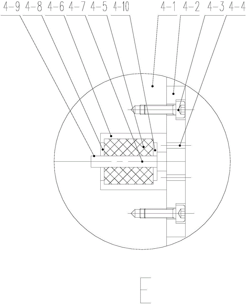
[0020] The piston assembly 4 includes a piston body 4-1, a cover plate 4-2, a mounting screw 4-3, an elastic body 4-5, a mandrel 4-7, a left gasket 4-8 and a right gasket 4-10, The middle part of the right side of the piston body 4-1 is provided with a compensation chamber 4-6; To the through hole, the right end of the mandrel 4-7 has a boss, and the right gasket 4-10, the elastic body 4-5 and the left gasket 4-8 are sequentially sleeved on the mandrel, and the mandrel The left end of 4-7 is inserted in...


PUM


Abstract

The invention discloses a hydraulic damper with a rigidity adjusting function. The hydraulic damper with the rigidity adjusting function comprises a left pin head (1), a right end cover (2), a cylinder body (3), a piston assembly (4), a piston rod (5), a left end cover (6), a left pin head (7), a first valve group (10), a second valve group (11), an oil storage box assembly (14) and a plurality of oil channels. According to the hydraulic damper with the rigidity adjusting function, a rigidity compensating device is arranged on a piston of the hydraulic damper; the requirement on the rigidity in a drawing direction of the hydraulic damper is met by a method of adjusting the structural rigidity of the hydraulic damper or replacing a work oil liquid, and then the requirement on the rigidity in a pressing direction of the hydraulic damper is met by adjusting the rigidity compensating device which is arranged on the piston of the hydraulic damper, so that the requirements on the rigidity in both drawing and pressing directions of the hydraulic damper are met. The hydraulic damper with the rigidity adjusting function is simple in structure and works reliably, can meet the requirements on the rigidity in both drawing and pressing directions of the hydraulic damper, and has a broad application prospect.

Description

technical field [0001] The invention relates to a hydraulic damper, in particular to a hydraulic damper with a stiffness adjusting device, which belongs to the technical field of electric and electromechanical. Background technique [0002] At present, hydraulic dampers are widely used in the field of anti-vibration and shock absorption. For ordinary hydraulic dampers, their stiffness is mainly determined by the structural stiffness of the hydraulic damper and the stiffness of the working oil. Once a hydraulic damper of a certain specification After the design is completed and the working oil is determined, its stiffness is basically determined. Through theoretical analysis and experiments, it can be known that the stiffness of the hydraulic damper in the tension and compression direction is inconsistent. Generally speaking, the stiffness of the hydraulic damper in the tension direction is higher than The stiffness in the compression direction is much smaller, which is its i...

Claims


Application Information

Patent Timeline
Patent Type & Authority Applications(China)
IPC IPC(8): F16F9/19F16F9/32F16F9/34F16F9/44
CPCF16F9/19F16F9/3214F16F9/3235F16F9/34F16F9/44F16F2228/066
Inventor 卢小青钱亚鹏卢格贺振宇倪忠贺枫袁艺胡安中沈伟钱雪松汤炳新
Owner 常州格林电力机械制造有限公司
Why Eureka
Try Eureka