Kaolin calcining furnace with illuminating lamp

A lighting lamp and calciner technology, which is applied in the calciner field, can solve the problems of inconvenient daily work, shortened service life, and high cost of the staff, and achieve the effects of shortening the calcining time, facilitating maintenance and replacement, and improving the service life

Active Publication Date: 2017-05-17
高州市兆翔新材料有限公司
View PDF5 Cites 0 Cited by
  • Summary
  • Abstract
  • Description
  • Claims
  • Application Information

AI Technical Summary

Problems solved by technology

[0002] The biggest defect of the existing kaolin calciner is that it is inconvenient to maintain, especially after the heating parts of each hearth are burnt out, the replacement is time-consuming and laborious, which brings great inconvenience to daily maintenance
[0003] In addition, the temperature of the material discharged from the kaolin calciner is relatively high, and generally it can only be bagged after natural cooling, so the efficiency is low
[0004] The existing kaolin calcining furnace starts calcining without cleaning the poor quality kaolin, so the products produced are of poor quality
[0005] In the existing kaolin calciner, the staff must stay beside the equipment, which brings great inconvenience to the daily work of the staff
[0006] When the kaolin calciner works at night, it needs lighting. In order to save electricity, LED lights are generally used. At present, the power factor correction (PFC) of the driving power used for LED lights is generally realized by an independent transformer. The constant current is realized by using a single 431 or two 431 or stable diodes; therefore, the PFC correction circuit used in the traditional drive power supply is more complicated, the number of components is relatively large, and the cost is high; and the output constant current accuracy is not high, generally within 3 %-10%, has a lot of negative effects on LED lamp beads, shortening the service life of LED

Method used


Image

  • Kaolin calcining furnace with illuminating lamp
  • Kaolin calcining furnace with illuminating lamp
  • Kaolin calcining furnace with illuminating lamp

Examples


Embodiment Construction

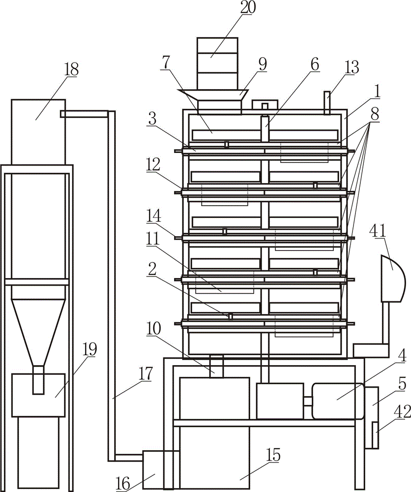
[0025] Such as figure 1 As shown, the kaolin calcining furnace with lighting lamp includes a furnace body 1, a temperature sensor 2, a heating electric film plate 3, a motor 4, an electric control box 5, a rotating shaft 6 and a pushing scraper 7, which 7 is made of stainless steel. The furnace body 1 has a plurality of hearths 8 distributed from top to bottom at intervals. The hearths 8 are fixed on the inner wall of the furnace body 1, and the top of the furnace body 1 is the feed inlet 9. The bottom is a discharge port 10. The rotating shaft 6 is vertically arranged in the center of the furnace body and passes through each of the hearths 8. The surface of the hearth 8 has a discharge port 11, and the adjacent hearths The blanking ports 11 are staggered, the pushing scraper 7 is parallel to the surface of the hearth 8, one end of the pushing scraper 8 is connected to the rotating shaft 6, the motor 4 is the power source of the rotating shaft 6, and the furnace body 1 is distri...


PUM


Abstract

The invention discloses a kaolin calcining furnace with an illuminating lamp. The kaolin calcining furnace comprises a furnace body, temperature sensors, heating electric membrane plates, a motor, an electric control cabinet, a rotary shaft, material pushing scrapers, the illuminating lamp and a constant-current drive power supply; the illuminating lamp is an LED lamp; and the constant-current drive power supply is composed of an EMC filtering module, a bridge type rectifier module, a pulse modulation and power factor correction module, an MOS tube, a transformer and a rectifier output module. As each heating electric membrane plate is formed by butt jointing two half parts, and each two half parts penetrate through electric membrane plate mounting holes formed in the two sides of the furnace body respectively and enter an interlayer of a furnace bottom, each heating electric membrane plate is greatly convenient to maintain and change; with adoption of a mode of remote monitoring, a worker can monitor equipment without being beside the equipment; and in the constant-current drive power supply, as PFC correction and DC-DC conversion can be realized by using a single transformer, the kaolin calcining furnace has the characteristics of simpleness in circuit, small amount of elements and low cost.

Description

Technical field [0001] The invention relates to a calciner, in particular to a kaolin calciner. Background technique [0002] The biggest defect of the existing kaolin calcining furnace is that it is inconvenient to maintain, especially after the heating parts of each hearth burn out, it takes time and effort to replace, which brings great inconvenience to daily maintenance. [0003] In addition, the temperature of the material discharged from the kaolin calciner is relatively high, and it is generally not bagged until it is naturally cooled, so the efficiency is low. [0004] The existing kaolin calcining furnace starts to calcinate the poor quality kaolin without cleaning, so the quality of the products produced is poor. [0005] In the existing kaolin calcining furnace, the staff must be guarded by the equipment, which brings great inconvenience to the staff's daily work. [0006] The kaolin calciner needs lighting when it works at night. In order to save electricity, LED lights are...

Claims


Application Information

Patent Timeline
Patent Type & Authority Applications(China)
IPC IPC(8): F27B1/04F27B1/09F27B1/10F27B1/20F27B1/26
CPCF27B1/005F27B1/04F27B1/08F27B1/10F27B1/20F27B1/26F27M2003/03
Inventor 莫崇兆
Owner 高州市兆翔新材料有限公司
Why Eureka
Try Eureka