Brake Caliper Test Bench

A technology of brake caliper and test bench, which is applied in the direction of railway vehicle testing, testing of mechanical components, testing of machine/structural components, etc. It can solve the problem of low assembly efficiency of brake caliper and improve the efficiency of assembly and positioning , Improve efficiency, improve the effect of installation and positioning efficiency

Active Publication Date: 2019-08-27
CRRC QINGDAO SIFANG ROLLING STOCK RES INST
View PDF5 Cites 0 Cited by
  • Summary
  • Abstract
  • Description
  • Claims
  • Application Information

AI Technical Summary

Problems solved by technology

[0006] Aiming at the technical problems that the test process of the existing caliper test bench does not match the actual braking process of the locomotive, and the low assembly efficiency of the brake caliper, the invention proposes a method that has accurate test results and greatly improves the assembly efficiency of the brake caliper. Tall brake caliper test bench

Method used


Image

  • Brake Caliper Test Bench
  • Brake Caliper Test Bench
  • Brake Caliper Test Bench

Examples


Embodiment Construction

[0028] Hereinafter, the present invention will be described in detail through exemplary embodiments. However, it should be understood that without further description, the elements, structures, and features in one embodiment can also be beneficially combined into other embodiments.

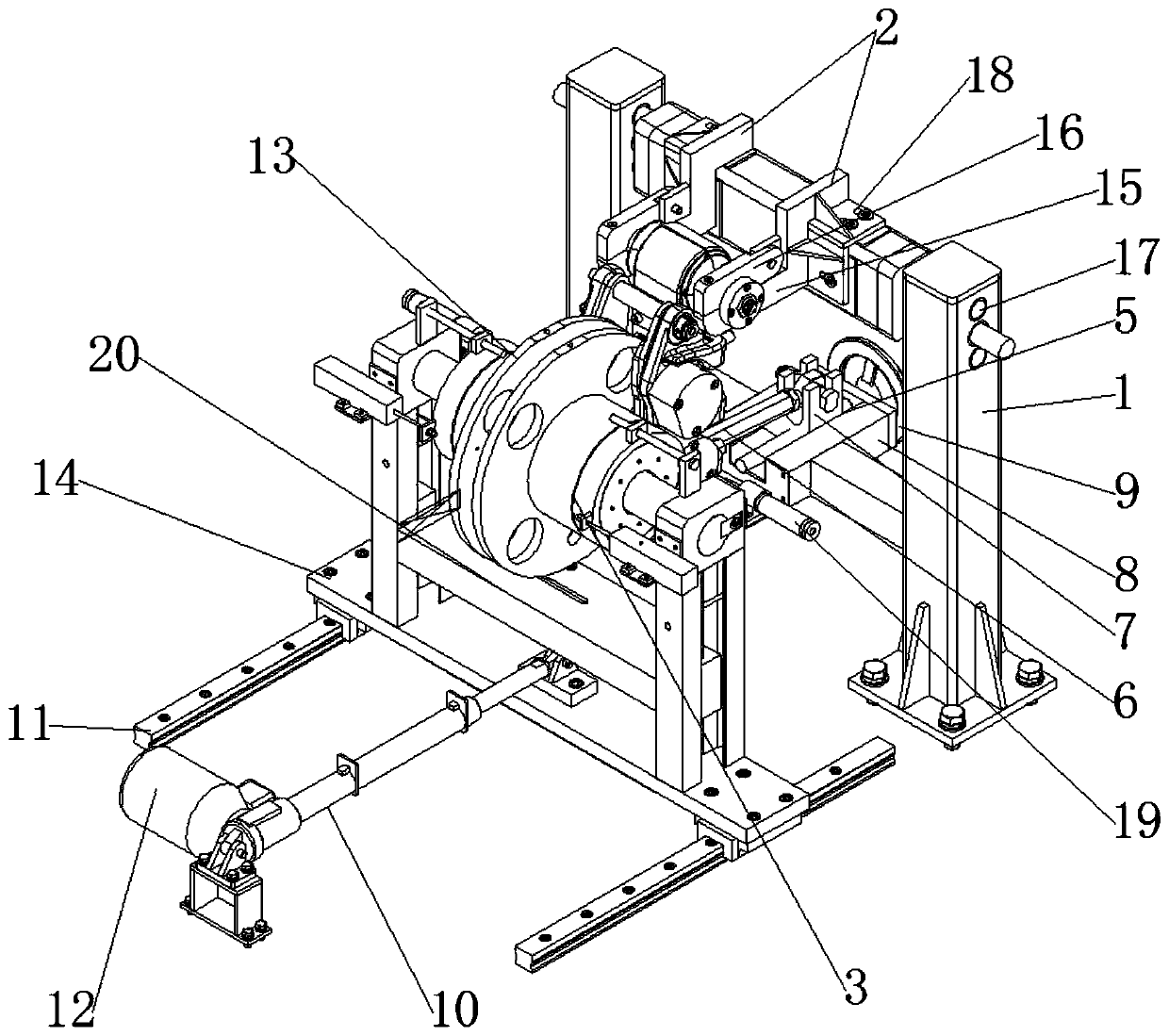
[0029] In the description of the present invention, it should be noted that the orientation or positional relationship indicated by the terms "upper" and "lower" are based on the attached Figure 5 The positional relationship shown is only for the convenience of describing the present invention and simplifying the description, rather than indicating or implying that the device or element referred to must have a specific orientation, be constructed and operated in a specific orientation, and therefore cannot be understood as a limitation of the present invention . In addition, the terms "first", "second", and "third" are only used for descriptive purposes, and cannot be understood as indicating or imp...


PUM


Abstract

The invention provides a brake clamp testbed. The brake clamp testbed comprises a support capable of fixing a brake clamp, and a rotary disc unit capable of linearly reciprocating in the direction vertical to the support. Two limiting units capable of hoisting the brake clamp are installed on the top of the support, first through holes capable of being connected with the two ends, in the clamping direction, of the brake clamp in a sleeving mode are formed in the limiting units, and the support is provided with a first driving unit capable of driving the brake clamp to rotate around the axes of the first through holes. The rotary disc unit comprises a rotary disc with the two side faces capable of being clamped by the brake clamp at the same time, and a second sliding base capable of supporting the two sides of the rotary disc. The second sliding base is connected with a second driving unit capable of driving the second sliding base to linearly move. The test result is accurate, and the assembly efficiency of the brake clamp is high.

Description

Technical field [0001] The invention belongs to the technical field of rail vehicle brake test equipment, and in particular relates to a brake caliper test bench. Background technique [0002] The brake caliper unit includes a brake caliper and a brake disc. It is generally used in high-speed railway locomotives, urban rail vehicles, ordinary railway passenger cars, high-speed EMUs and other railway rolling stocks that use disc brakes to achieve Common braking (including pneumatic braking and hydraulic braking) and parking braking of rail rolling stock. The above-mentioned disc brake is to install a brake disc on the axle or on the side of the wheel web, and use two brake pads made of synthetic material of the brake caliper to press against the side of the brake disc, thereby generating braking force through friction. To stop the train. [0003] The brake caliper test bench is used to test the performance of the brake caliper unit after delivery or after maintenance (including br...

Claims


Application Information

Patent Timeline
Patent Type & Authority Patents(China)
IPC IPC(8): G01M17/08G01M13/00
Inventor 孟艳红姜衍猛杜剑宇张昭英
Owner CRRC QINGDAO SIFANG ROLLING STOCK RES INST
Why Eureka
Try Eureka