Eureka AIR delivers breakthrough ideas for toughest innovation challenges, trusted by R&D personnel around the world.

Anemobiagraph for building

An anemometer and construction technology, which is applied in the field of construction devices, can solve the problems of lack of measurement warning devices, reducing the measurement accuracy of anemometers, and failing to warn users, etc.

Inactive Publication Date: 2017-05-17
CHENGDU JIAMEIJIA SCI & TECH
View PDF3 Cites 2 Cited by
  • Summary
  • Abstract
  • Description
  • Claims
  • Application Information

AI Technical Summary

Problems solved by technology

[0002] With the continuous development of the construction industry and the continuous expansion of construction projects, the types of construction equipment are becoming more and more abundant. Many people have paid more attention to measuring the environmental conditions around the building. Therefore, anemometers are more and more popular among people. The measurement of the natural environment is objective to a certain extent, so special attention should be paid to the measurement. The general anemometer uses the measuring device to measure at a fixed height, which limits the function of the anemometer to a certain extent. , reduce the measurement accuracy of the anemometer, and because the general anemometer only has a simple observation device and lacks a measurement warning device, the structure and function of the observation device are incomplete to a certain extent, and the function of warning the user cannot be achieved.

Method used


Image

  • Anemobiagraph for building
  • Anemobiagraph for building
  • Anemobiagraph for building

Examples


Embodiment Construction

[0014] The specific embodiments of the present invention will be further described below in conjunction with the accompanying drawings. It should be noted here that the descriptions of these embodiments are used to help understand the present invention, but are not intended to limit the present invention. In addition, the technical features involved in the various embodiments of the present invention described below may be combined with each other as long as they do not constitute a conflict with each other.

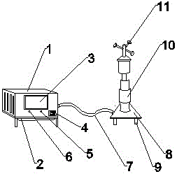
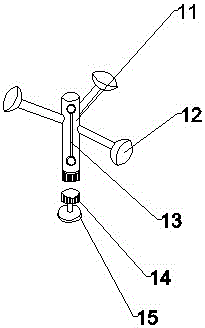
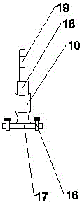
[0015] see Figure 1 to Figure 4 , the present invention provides a technical solution: an anemometer for construction, including a working platform 2, including an observation device 1, an LCD display screen 3, an indicator light 6, a warning device 5, a working switch 4, an optical fiber 7. The base 8, the feet 9, the pillar 10, and the measuring device 11. An observation device 1 is installed directly above the working platform 2, and the measurement range of the obs...


PUM


Abstract

The present invention discloses an anemobiagraph for a building. The anemobiagraph for the building comprises a working platform, an observation device is installed at the upper portion of the working platform, the outer surface of the observation device is provided with a LCD display screen, the lower portion of the LCD display screen is provided with an indicator light, the right side of the indicator light is provided with an annunciator, the right side of the annunciator is provided with an operating switch, the right side of the observation device is provided with an optical fiber, the right side of the optical fiber is provided with a pedestal and a support arm, the lower portion of the pedestal is provided with a support arm, the upper portion of the pedestal is provided with a supporting column, and the upper portion of the supporting column is provided with a measurement device. The anemobiagraph for a building is provided with the observation device and coordinates with the LCD display screen to allow users to perform visual observation and analysis of the measured data so as to ensure the integration and unity of the observation and the measurability of the anemobiagraph, and is provided with the indicator light and coordinates with the annunciator to allow the observation device to prompt users when it is detected that the periphery around the users has heavy wind so as to ensure safety of the users and devices.

Description

technical field [0001] The invention relates to the technical field of construction devices, in particular to an anemometer for construction. Background technique [0002] With the continuous development of the construction industry and the continuous expansion of construction projects, the types of construction equipment are becoming more and more abundant. Many people have paid more attention to measuring the environmental conditions around the building. Therefore, anemometers are more and more popular among people. The measurement of the natural environment is objective to a certain extent, so special attention should be paid to the measurement. The general anemometer uses the measuring device to measure at a fixed height, which limits the function of the anemometer to a certain extent. , reduce the measurement accuracy of the anemometer, and because the general anemometer only has a simple observation device and lacks a measurement warning device, the structure and funct...

Claims


Application Information

Patent Timeline
Patent Type & Authority Applications(China)
IPC IPC(8): G01P5/07G08C17/02G08C23/06
CPCG08C17/02G08C23/06G01P5/07
Inventor 秦熙珍
Owner CHENGDU JIAMEIJIA SCI & TECH
Why Eureka
Eureka Blog
Learn More