Circuit for transistor level implementation scheme of five input end combination logical circuit

A combinational logic circuit, transistor-level technology, applied in logic circuits, logic circuits with logic functions, electrical components, etc., can solve the problems of large transmission delay, high circuit cost, large signal transmission delay, etc., and achieve the reduction of silicon chip area. , the effect of reducing the number of transistors

Inactive Publication Date: 2017-05-17
HEFEI HENGSHUO SEMICON CO LTD
0 Cites 0 Cited by

AI-Extracted Technical Summary

Problems solved by technology

[0005] Second, the signal transmission delay is large
The transmission delay from input to output is too large, and it will be fatal for circuits with high frequency, which are very concerned about the...

Abstract

The invention discloses a circuit for a transistor level implementation scheme of a five input end combination logical circuit. The circuit comprises a first triode, a second triode, a third triode, a fourth triode, a fifth triode, a sixth triode, a seventh triode and the like, a grid electrode of the first triode is connected with a grid electrode of the sixth triode, a source electrode of the first triode is connected with a drain electrode of the second triode, a grid electrode of the second triode is connected with a grid electrode of the seventh triode, a source electrode of the second triode is connected with a drain electrode of the third triode, a grid electrode of the third triode is connected with a grid electrode of an eighth triode, a grid electrode of the fourth triode is connected with a grid electrode of a ninth triode, a source electrode of the fourth triode is connected with a drain electrode of the fifth triode, and a grid electrode of the fifth triode is connected with a grid electrode of a thirteenth triode. Accordingly, the number of transistors is reduced, the purpose of reducing the number of the transistors is achieved, and finally the purpose of greatly reducing the silicon area occupied by the same logical function is achieved.

Application Domain

Logic circuits characterised by logic function

Technology Topic

Logical circuitEngineering +6

Image

  • Circuit for transistor level implementation scheme of five input end combination logical circuit
  • Circuit for transistor level implementation scheme of five input end combination logical circuit

Examples

  • Experimental program(1)

Example Embodiment

[0016] Hereinafter, preferred embodiments of the present invention are given in conjunction with the drawings to illustrate the technical solutions of the present invention in detail.
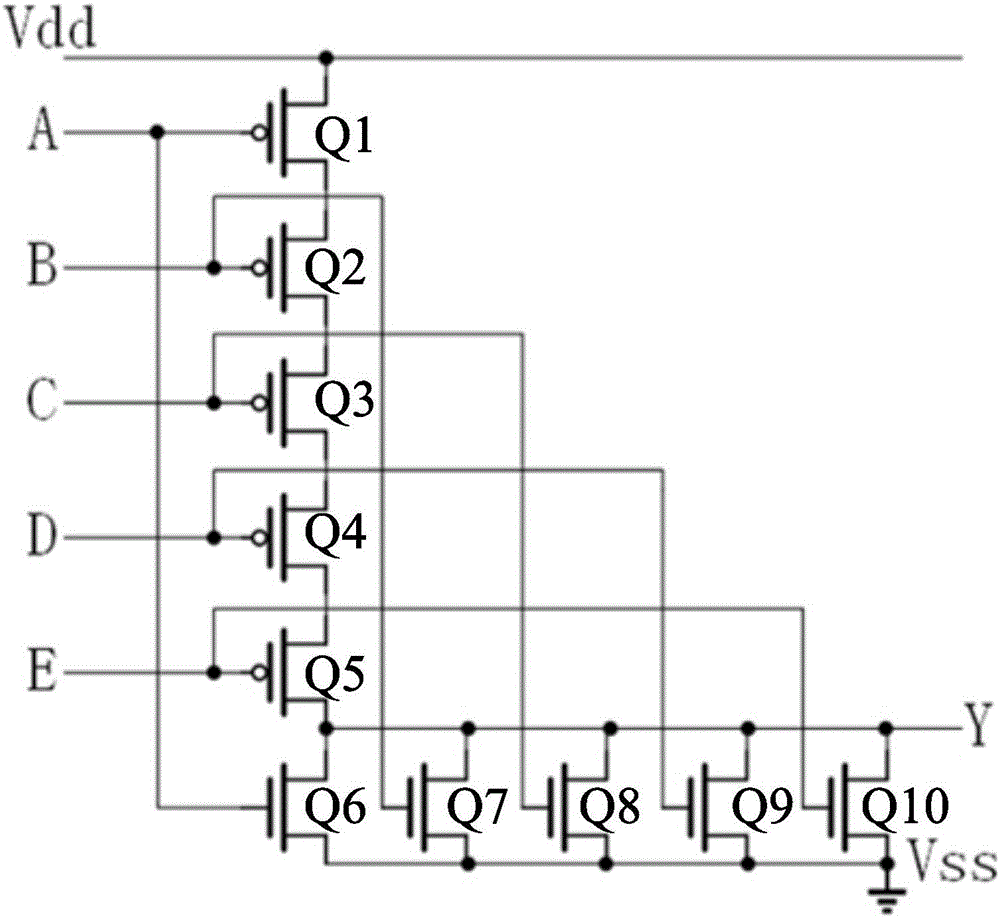
[0017] Such as figure 1 As shown, the circuit of the transistor-level implementation scheme of the five-input combinational logic circuit of the present invention includes a first triode Q1, a second triode Q2, a third triode Q3, a fourth triode Q4, and a fifth triode. The transistor Q5, the sixth transistor Q6, the seventh transistor Q7, the eighth transistor Q8, the ninth transistor Q9, the thirteenth transistor Q10, the gate and the first transistor Q1 The gate of the six transistor Q6 is connected, the source of the first transistor Q1 is connected to the drain of the second transistor Q2, the gate of the second transistor Q2 and the gate of the seventh transistor Q7 are connected Connected, the source of the second transistor Q2 is connected to the drain of the third transistor Q3, the gate of the third transistor Q3 is connected to the gate of the eighth transistor Q8, and the third transistor Q3 The source of the fourth transistor Q4 is connected to the drain of the fourth transistor Q4, the gate of the fourth transistor Q4 is connected to the gate of the ninth transistor Q9, and the source of the fourth transistor Q4 is connected to the fifth transistor. The drain of the transistor Q5 is connected, the gate of the fifth transistor Q5 is connected to the gate of the thirteenth transistor Q10, the source of the fifth transistor Q5, the drain of the sixth transistor Q6, and the seventh The drain of the transistor Q7, the drain of the eighth transistor Q8, the drain of the ninth transistor Q9 and the drain of the thirteenth transistor Q10 are connected, and the source of the sixth transistor Q6, The source of the seventh transistor Q7, the source of the eighth transistor Q8, the source of the ninth transistor Q9, and the source of the thirteenth transistor Q10 are connected and grounded.
[0018] The first triode Q1, the second triode Q2, the third triode Q3, the fourth triode Q4, and the fifth triode Q5 are all PMOS transistors.
[0019] The sixth transistor Q6, the seventh transistor Q7, the eighth transistor Q8, the ninth transistor Q9, and the thirteenth transistor Q10 are all NMOS transistors.
[0020] The working principle of the present invention is as follows: the present invention can make the implementation scheme into a standard cell (standard cell), so as to facilitate the call in future use.
[0021] In summary, the present invention reduces the number of transistors. The number of transistors is reduced from 18 to 10. This achieves the purpose of reducing the number of transistors, and finally achieves the goal of greatly reducing the silicon area occupied by the same logic function. .
[0022] The specific embodiments described above further describe the technical problems, technical solutions, and beneficial effects solved by the present invention in further detail. It should be understood that the above descriptions are only specific embodiments of the present invention and are not intended to limit In the present invention, any modification, equivalent replacement, improvement, etc., made within the spirit and principle of the present invention should be included in the protection scope of the present invention.

PUM

no PUM

Description & Claims & Application Information

We can also present the details of the Description, Claims and Application information to help users get a comprehensive understanding of the technical details of the patent, such as background art, summary of invention, brief description of drawings, description of embodiments, and other original content. On the other hand, users can also determine the specific scope of protection of the technology through the list of claims; as well as understand the changes in the life cycle of the technology with the presentation of the patent timeline. Login to view more.

Similar technology patents

Circuit for implementing transistor-level scheme of five-input-end combinational logic circuit

InactiveCN106685399AReduce Transistor CountWafer Area Reduction
Owner:HEFEI HENGSHUO SEMICON CO LTD

Complementary-type SCR (Silicon Controlled Rectifier) structure triggered by diode string in an auxiliary way

InactiveCN101771040ALower the trigger voltageWafer Area Reduction
Owner:ZHEJIANG UNIV

Circuit of transistor-grade realizing solution of five-input-end combined logic circuit

InactiveCN106685405AReduce Transistor CountWafer Area Reduction
Owner:HEFEI HENGSHUO SEMICON CO LTD

Circuit for transistor level implementation scheme of five input end combination logical circuit

InactiveCN106685404AReduce Transistor CountWafer Area Reduction
Owner:HEFEI HENGSHUO SEMICON CO LTD

Classification and recommendation of technical efficacy words

  • Reduce Transistor Count
  • Wafer Area Reduction

Circuit for implementing transistor-level scheme of five-input-end combinational logic circuit

InactiveCN106685399AReduce Transistor CountWafer Area Reduction
Owner:HEFEI HENGSHUO SEMICON CO LTD

Circuit for transistor level implementation scheme of five input end combination logical circuit

InactiveCN106685404AReduce Transistor CountWafer Area Reduction
Owner:HEFEI HENGSHUO SEMICON CO LTD

Circuit of transistor-grade realizing solution of five-input-end combined logic circuit

InactiveCN106685405AReduce Transistor CountWafer Area Reduction
Owner:HEFEI HENGSHUO SEMICON CO LTD

Complementary-type SCR (Silicon Controlled Rectifier) structure triggered by diode string in an auxiliary way

InactiveCN101771040ALower the trigger voltageWafer Area Reduction
Owner:ZHEJIANG UNIV

Circuit for implementing transistor-level scheme of five-input-end combinational logic circuit

InactiveCN106685399AReduce Transistor CountWafer Area Reduction
Owner:HEFEI HENGSHUO SEMICON CO LTD

Circuit for transistor level implementation scheme of five input end combination logical circuit

InactiveCN106685404AReduce Transistor CountWafer Area Reduction
Owner:HEFEI HENGSHUO SEMICON CO LTD

Circuit of transistor-grade realizing solution of five-input-end combined logic circuit

InactiveCN106685405AReduce Transistor CountWafer Area Reduction
Owner:HEFEI HENGSHUO SEMICON CO LTD
Why Eureka
Try Eureka