Pixel sharing-based PWM driving circuit and driving method

A driving circuit and driving method technology, applied in the direction of electrical components, instruments, static indicators, etc., can solve the problems of high process stability and quality requirements, a large number of transistors, high manufacturing costs, etc., and achieve the drive area and resolution. Effects of limitation, reduction in transistor count, and reduction in manufacturing cost

Active Publication Date: 2021-11-19
NANJING UNIV
View PDF11 Cites 0 Cited by
  • Summary
  • Abstract
  • Description
  • Claims
  • Application Information

AI Technical Summary

Problems solved by technology

[0003]The current pixel drive circuit requires a signal processing module for each light-emitting unit, which leads to a big disadvantage: for high-density pixel arrays, the drive circuit

Method used


Image

  • Pixel sharing-based PWM driving circuit and driving method
  • Pixel sharing-based PWM driving circuit and driving method
  • Pixel sharing-based PWM driving circuit and driving method

Examples


Embodiment Construction

[0030] The present invention will be further described below in conjunction with the embodiments and accompanying drawings.

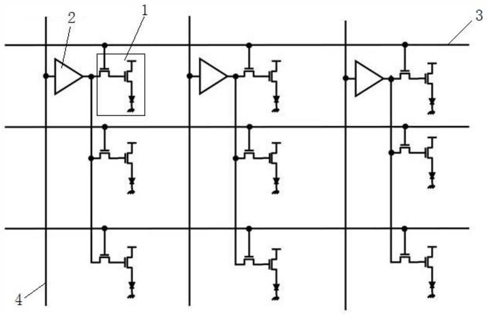
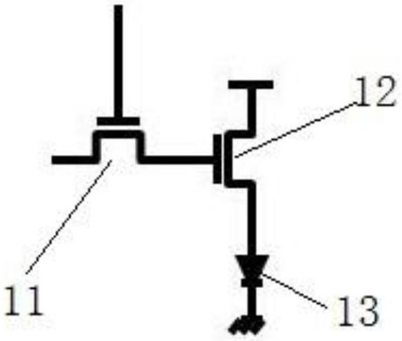
[0031] see figure 1 The shown PWM drive circuit based on pixel sharing includes light-emitting units 1 arranged in a rectangular array; corresponding to each column of light-emitting units 1, it also includes a signal processing module 2 and a second signal connected to the signal processing module 2 Transmitter 4, any light-emitting unit 1 in each column is signal-connected to signal processing module 2; corresponding to each row of light-emitting units 1, it also includes a first signal transmitter 3, any light-emitting unit 1 in each row is connected to the first signal transmitter 1 signal connection.

[0032] Wherein, the signal processing module 2 is a module shared by columns, the second signal transmitter 4 provides signals for the signal processing module 2, and the signal processing module 2 can provide driving signals for all light-emitting ...


PUM


Abstract

The invention discloses a PWM driving circuit and driving method based on pixel sharing, and the PWM driving circuit comprises a plurality of light-emitting units arranged in an array. The PWM driving circuit further comprises a signal processing module which is corresponding to each column of light-emitting units and is used for providing PWM driving signals, wherein any one light-emitting unit in each column is in signal connection with the signal processing module; the PWM driving circuit further comprises a first signal emitter which is corresponding to each row of light-emitting units and used for providing switching signals, wherein any one light-emitting unit in each row is in signal connection with the first signal emitter. On the basis of the pixel sharing principle, the multiple light-emitting units share one signal processing module, the average transistor number of each driving circuit is remarkably reduced, the integration difficulty and the preparation cost are greatly reduced, and pixel driving with low transistor density is achieved.

Description

technical field [0001] The present invention relates to Micro LED PWM driving, specifically a PWM driving circuit and a driving method based on pixel sharing. Background technique [0002] For the pixel array, the traditional driving method is to realize the generation of the driving signal through the peripheral circuit, and directly add the signal to the light-emitting unit array through wordline and bitline to realize the driving of the light-emitting unit. Different from the traditional driving circuit, the pixel driving circuit realizes the processing of the peripheral signal through the driving circuit integrated with each pixel light-emitting unit (such as LED), so as to realize the driving of the light-emitting unit. Since the signal processing module is very close to the light emitting unit, the quality of the driving signal obtained in this way is higher. [0003] The current pixel drive circuit requires a signal processing module for each light-emitting unit, whi...

Claims


Application Information

Patent Timeline
IPC IPC(8): G09G3/32H05B45/325
CPCG09G3/32H05B45/325G09G2320/0233
Inventor 王欣然毛赟邱浩施毅
Owner NANJING UNIV
Why Eureka
Try Eureka