Decoding voltage conversion device and digital analog converter employing same

A converter and switcher technology, applied in the direction of digital-to-analog converters, etc., can solve the problems of increasing power consumption, increasing layout area, etc., and achieve the effects of reducing power consumption, reducing cost, and reducing the number of transistors

Active Publication Date: 2015-11-25
FOCALTECH ELECTRONICS
View PDF5 Cites 0 Cited by
  • Summary
  • Abstract
  • Description
  • Claims
  • Application Information

AI Technical Summary

Problems solved by technology

Therefore, the existing technology goes through the decoder 110 to the transformer (LS) 120, in addition to increasing the layout area, i

Method used


Image

  • Decoding voltage conversion device and digital analog converter employing same
  • Decoding voltage conversion device and digital analog converter employing same
  • Decoding voltage conversion device and digital analog converter employing same

Examples


Embodiment Construction

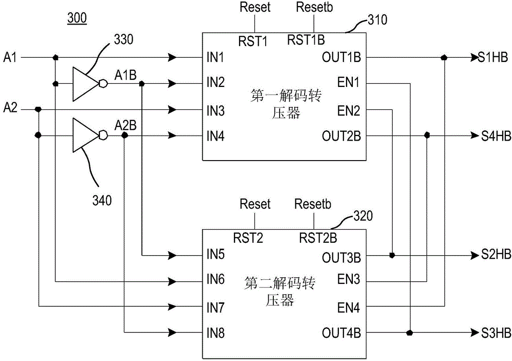
[0040] image 3 It is a system block diagram of a decoding and converting device 300 of the present invention, which includes a first decoding and converting device 310 and a second decoding and converting device 320 , a first inverter 330 and a second inverter 340 . The first decoding converter 310 has first to fourth input terminals (IN1, IN2, IN3, IN4), a first output terminal (OUT1B), a second output terminal (OUT2B), a first enabling terminal (EN1 ), the second enabling terminal (EN2), the first reset input terminal (Rst1), and the second reset input terminal (Rst1B), the first to fourth input terminals (IN1, IN2, IN3, IN4) Respectively receive the first signal (A1), the first inverted signal (A1B), the second signal (A2), and the second inverted signal (A2B). The second decoding converter 320 has fifth to eighth input terminals (IN5, IN6, IN7, IN8), a third output terminal (OUT3B), a fourth output terminal (OUT4B), a third enabling terminal (EN3 ), and the fourth enabl...


PUM


Abstract

The invention provides a decoding voltage conversion device and a digital analog converter employing the same. The device comprises a first decoding voltage converter and a second decoding voltage converter. The first decoding voltage converter is provided with a first input end, a second input end, a third input end, a fourth input end, a first output end, a second output end, a first enable end, a second enable end, a first reset input end, and a second reset input end. The first, second, third and fourth input ends receive a first signal, a second signal, and inverted phase signals thereof. The second decoding voltage converter is provided with a fifth input end, a sixth input end, a seventh input end, an eighth input end, a third output end, a fourth output end, a third enable end, and a fourth enable end. The fifth, sixth, seventh and eighth input ends receive the first signal, the second signal and the inverted phase signals thereof.

Description

technical field [0001] The invention relates to the technical fields of voltage conversion and digital-to-analog conversion, in particular to a decoding and converting device and a digital-to-analog converter using the decoding and converting device. Background technique [0002] Voltage conversion circuits are usually used to convert low-voltage control signals into high-voltage control signals. For example, when applied to liquid crystal displays, it is usually necessary to convert digital control signals from low voltage to high voltage to drive thin-film transistors. The corresponding operation needs to be completed through a voltage conversion circuit. [0003] figure 1 It is a schematic diagram of the existing decoding and converting device 100. When the data A[1:0] is input, its high potential and low potential are respectively VCC and VSS. After passing through the decoder 110, decoding signals S0-S3 are respectively generated, wherein The high potentials and low p...

Claims


Application Information

Patent Timeline
IPC IPC(8): H03M1/66
Inventor 郑彦诚
Owner FOCALTECH ELECTRONICS
Why Eureka
Try Eureka