Oblique photographing device for high-definition unmanned aerial vehicle

A technology of oblique photography and unmanned aerial vehicles, which is applied in the directions of unmanned aerial vehicles, motor vehicles, transportation and packaging, etc., can solve the problem of increasing operation time, cost and operation risk, unsatisfactory photo clarity, and increasing the intensity of shooting operations, etc. problems, to improve the clarity and probability of successful shooting, high reliability, and easy operation.

Inactive Publication Date: 2017-05-17
WENZHOU UNIVERSITY
View PDF6 Cites 4 Cited by
  • Summary
  • Abstract
  • Description
  • Claims
  • Application Information

AI Technical Summary

Problems solved by technology

Traditional oblique photography uses five cameras to shoot multiple angles of ground features at a certain installation angle, so as to obtain true 3D image data of ground features. Today's drones have a difficult installation problem in terms of load. In the existing technology, 3 cameras are also used for cross-flying. Although the weight of the camera is reduced, the workload of the flight is doubled and increased. cost of operating time and operating risk
[0003] In addition, due to the fact that the UAV is always in flight during the aerial shooting process, and there is also the influence of the wind, the shake of the lens is inevitable. As a result, the stability of the lens is low during shooting, resulting in insufficient clarity of some photos taken, and it is necessary to take off again. The human-machine re-shoots again, which greatly increases the intensity of the shooting operation and reduces work efficiency
Half of the prior art is to avoid and solve this problem by increasing the shooting time, but this method increases the cost of time and equipment. In addition, the stability of the lens is still poor, and the clarity of some photos taken is still not ideal. Therefore, there is an urgent need for a low-cost, tilting photography device for drones with a stable lens during shooting, that is, a tilting photography device for high-definition drones to buffer and stabilize the photography lens

Method used


Image

  • Oblique photographing device for high-definition unmanned aerial vehicle
  • Oblique photographing device for high-definition unmanned aerial vehicle
  • Oblique photographing device for high-definition unmanned aerial vehicle

Examples


Embodiment Construction

[0016] In order to make the technical means, creative features, goals and effects achieved by the present invention easy to understand, the present invention will be further described below in conjunction with specific embodiments.

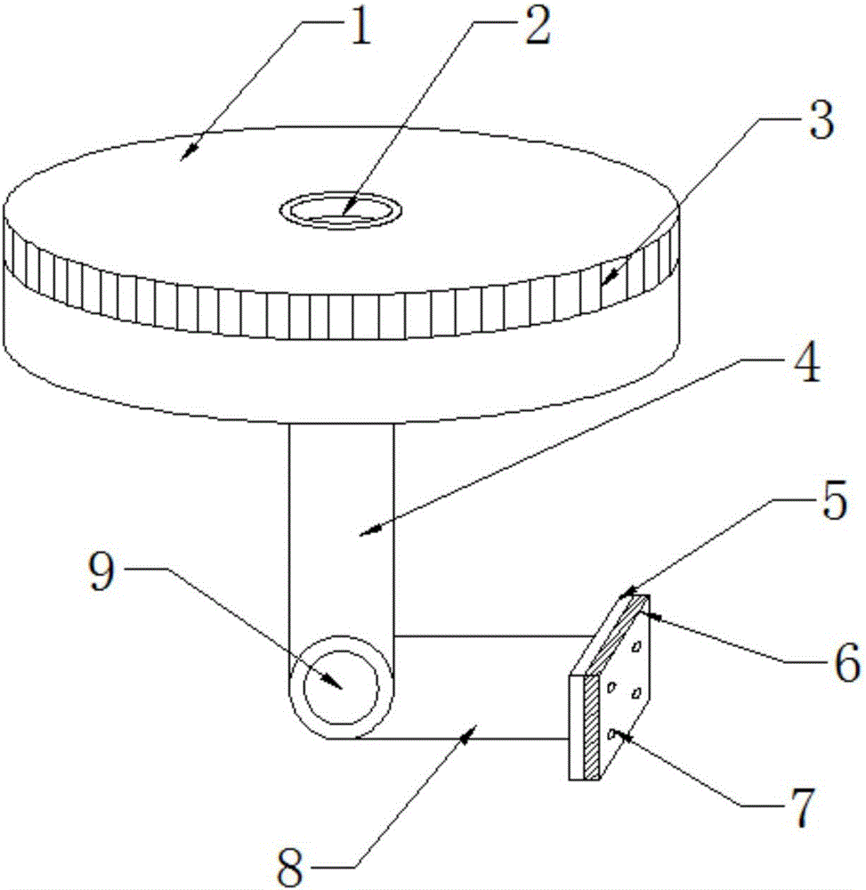
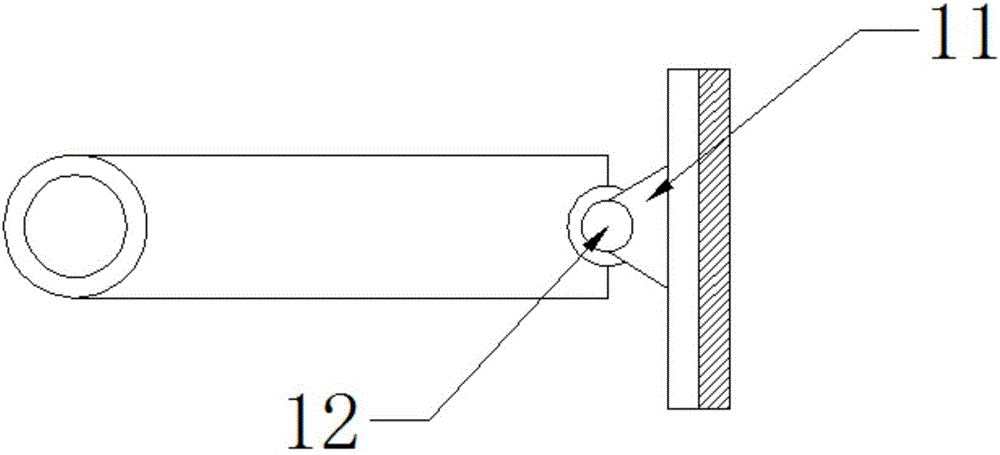
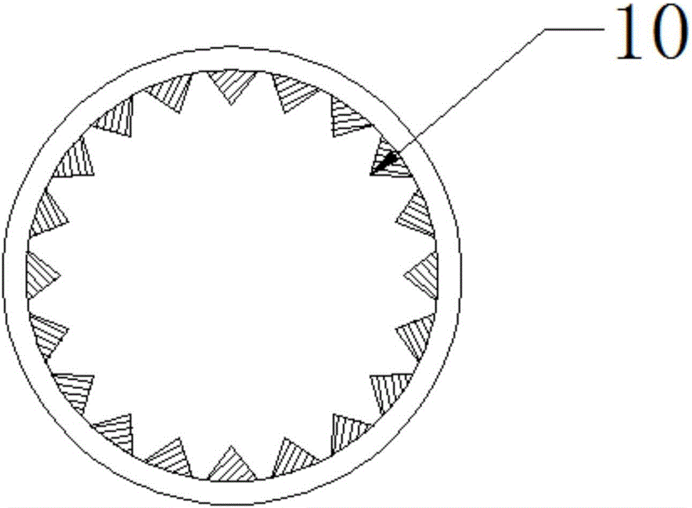
[0017] see figure 1 , figure 2 and image 3 , the present invention provides a technical solution: a tilting photography device for high-definition drones, including a fixed structure and a rotating structure, the fixed structure includes a rotating disk 1, a fixed shaft seat 2, a rack 3, a connecting rod 4 and a motor 9, The rotating disk 1 is a cylindrical disk-shaped structure, and the middle position of the rotating disk 1 is equipped with a fixed shaft seat 2, and the fixing of the present invention is realized by adding the fixed shaft seat 2. This design effectively improves the stability of the present invention, and the rack The design of 3 is convenient for the controller to control the rotation angle of the rotating disk 1 by control...


PUM


Abstract

The invention provides an oblique photographing device for a high-definition unmanned aerial vehicle. A rotating disc is of a cylindrical disc structure, a fixing shaft base is installed in the middle of the rotating disc, a rack is assembled at the position at the upper end of the side face of the rotating disc and arranged around one circle of the rotating disc, a connecting rod is installed in the middle of the lower end face of the rotating disc, the axle wire of the connecting rod is perpendicular to the lower end face of a base, the oblique photographing device is fixed by adding the fixing shaft base, and due to the design of the rack, a control worker can control a rotating motor to rotate conveniently so as to control the rotating angle of the rotating disc; in addition, the connecting rod and a rotating rod are installed through the motor, so that rotation of a camera is controlled conveniently, 360-degree photographing is achieved in cooperation with the rotating motor; due to the design of a rubber plate, direct hard contact between the camera and a fixing plate is avoided; due to the design, the problem that traditional photographing devices need to be fixed by soft cushions is solved; due to the design of an installation base and a rotating shaft, the angle of the fixing plate can be freely adjusted.

Description

technical field [0001] The invention is an oblique photographing device for a high-definition unmanned aerial vehicle, which belongs to the field of unmanned aerial vehicle equipment. Background technique [0002] In the existing technology, with the development of UAV technology, its application field is continuously expanding, from traditional UAV aerial photogrammetry to gradually extending to oblique photography to realize three-dimensional modeling. Traditional oblique photography uses five cameras to shoot multiple angles of ground features at a certain installation angle, so as to obtain true 3D image data of ground features. Today's drones have a difficult installation problem in terms of load. In the existing technology, 3 cameras are also used for cross-flying. Although the weight of the camera is reduced, the workload of the flight is doubled and increased. The cost of operating time and operating risk. [0003] In addition, due to the fact that the UAV is alway...

Claims


Application Information

Patent Timeline
Patent Type & Authority Applications(China)
IPC IPC(8): H04N5/232
CPCH04N23/68B64U2101/30
Inventor 胡铸鑫
Owner WENZHOU UNIVERSITY
Why Eureka
Try Eureka