Electronic equipment and overturning mechanism thereof

A flipping mechanism and technology for electronic equipment, applied in the direction of mechanical equipment, support structure installation, support structure on hinges/pivots, etc., can solve the effect of electronic equipment self-locking performance maintenance effect, friction reduction, electronic equipment work performance drop and other issues

Active Publication Date: 2017-05-17
LENOVO (BEIJING) CO LTD
View PDF6 Cites 6 Cited by
  • Summary
  • Abstract
  • Description
  • Claims
  • Application Information

AI Technical Summary

Problems solved by technology

However, in the above-mentioned overturning mechanism, since the locking piece of the self-locking structure and the bowl-shaped elastic piece of the torsion structure are arranged in a plane perpendicular to the axis of the rotating shaft, the friction force generated by mutual friction and extrusion provides self-locking for electronic equipment. Force and protection, so it is necessary to ensure that the contact area between the self-locking piece and the bowl-shaped shrapnel in the plane perpendicular to the shaft axis is large enough to generate sufficient friction, and if the overall size of the turning mechanism is reduced, the self-locking piece The contact area with the bowl-shaped shrapnel will inevitably decrease, resulting in a decrease in the friction between the self-locking piece and the bowl-shaped shrapnel, which will affect the self-locking performance of the electronic device and the maintenance effect of the flipped shape, making the working performance of the electronic device decline

Method used


Image

  • Electronic equipment and overturning mechanism thereof
  • Electronic equipment and overturning mechanism thereof
  • Electronic equipment and overturning mechanism thereof

Examples


Embodiment Construction

[0035] The invention provides an overturning mechanism, which will not reduce the working performance of the electronic equipment when the overall size of the electronic equipment is reduced.

[0036] The following will clearly and completely describe the technical solutions in the embodiments of the present invention with reference to the accompanying drawings in the embodiments of the present invention. Obviously, the described embodiments are only some, not all, embodiments of the present invention. Based on the embodiments of the present invention, all other embodiments obtained by persons of ordinary skill in the art without making creative efforts belong to the protection scope of the present invention.

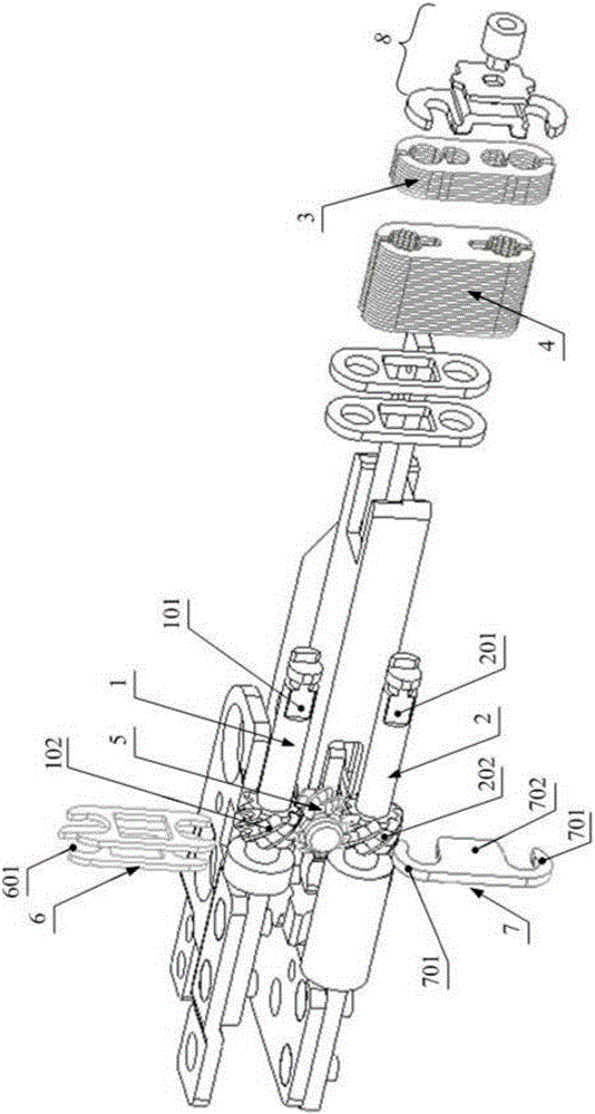
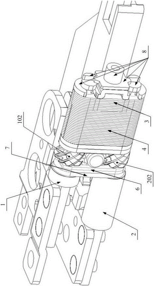
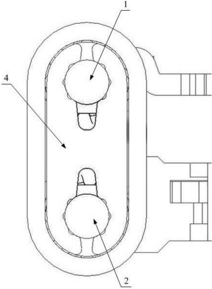
[0037] Such as Figure 1-Figure 5 As shown, the turning mechanism provided by the embodiment of the present invention includes a rotating shaft and a self-locking member 3, which constitute the self-locking structure of the turning mechanism. Among them, the rotating s...


PUM


Abstract

The application discloses an overturning mechanism. The overturning mechanism is used for rotating connection of a first part and a second part which can be opened and closed by overturning on electronic equipment. The overturning mechanism comprises a rotary shaft and a self-locking part, wherein the rotary shaft is rotatably connected with the first part and the second part; the self-locking part is sheathed on the rotary shaft and is in frictional contact with the rotary shaft; and with the rotation of the rotary shaft, the rotational friction generated between the self-locking part and the rotary shaft is increased gradually. The overturning mechanism disclosed by the invention has the advantages that compared with the existing mode for obtaining the friction by a plane vertical to the axis of the rotary shaft, since the self-locking part is sheathed on the rotary shaft and is in frictional contact with the rotary shaft, the rotational friction generated by the self-locking part and the rotary shaft is distributed along the circumferential direction of the rotary shaft, so that even though the size of the plane of the self-locking part is reduced, the size of the friction between the rotary shaft and the self-locking part sheathed thereon is also influenced, the working performance of the electronic equipment also can not be reduced when the whole size of the electronic equipment is reduced, even the working performance of the electronic equipment can be further improved. The invention also provides the electronic equipment with the overturning mechanism.

Description

technical field [0001] The present invention relates to the technical field of electronic equipment, in particular to an overturn mechanism, and also relates to an electronic equipment with the above overturn mechanism. Background technique [0002] In reversible electronic devices such as notebook computers and mobile phones, the screen part and the host part are rotatably connected through a reversing mechanism. [0003] In the prior art, the turning mechanism capable of realizing the 360-degree turning of the screen part relative to the host part generally includes a transmission structure, a torsion structure and a self-locking structure, wherein the function of the transmission structure is to realize the synchronous rotation of the screen part and the host part, The function of the torsion structure is to provide a holding force for the screen part to stay in the flipped position after being turned over, and the function of the self-locking structure is to ensure that ...

Claims


Application Information

Patent Timeline
IPC IPC(8): H05K7/16F16C11/04
CPCH05K7/16F16C11/045
Inventor 罗军超
Owner LENOVO (BEIJING) CO LTD
Why Eureka
Try Eureka