
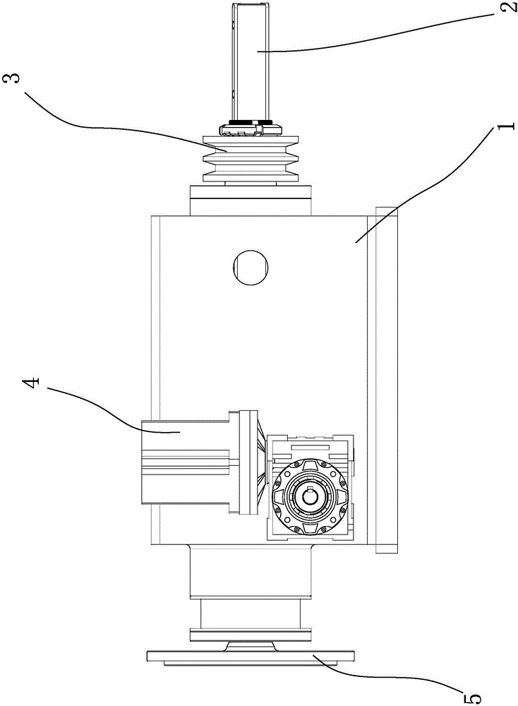
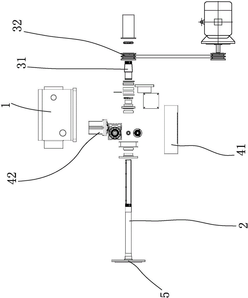
Tile dry cast machine grinding head structure

A technology of dry polishing and grinding head, which is applied in the direction of grinding head, surface polishing machine tool, grinding drive device, etc. It can solve the problems of workpiece stepped grinding marks, poor polishing effect, workpiece breakage, etc., and achieve simple operation and improved Good grinding output, quality and stability

Inactive Publication Date: 2017-05-24
佛山市铭创科技有限公司
View PDF5 Cites 0 Cited by
  • Summary
  • Abstract
  • Description
  • Claims
  • Application Information

AI Technical Summary

Problems solved by technology

[0003] In order to make the resin grinding wheel press tightly on the processing surface of the workpiece during polishing, it is usually necessary to install a lifting mechanism or device that can lift the grinding wheel in the equipment responsible for polishing in the above-mentioned processing machinery, so that during operation, the wear of the grinding wheel becomes smaller. Finally, the gap between the machined surface and the workpiece is compensated. In the traditional technology, this lifting mechanism is equipped with a rotating shaft and a motor on the polishing machine base. The rotating shaft and the motor are connected by a belt, and a grinding wheel is installed at one end of the rotating shaft. After being connected to the frame and connected with the piston rod of the cylinder, or the polishing base is completely supported by the piston rod of the cylinder, the polishing base can be flipped or raised and lowered by manually operating the expansion and contraction of the cylinder to achieve the lifting and lowering of the grinding wheel. Purpose, this technology theoretically meets the aforementioned gap compensation requirements, but in practical applications, the polishing effect is not good, because the cylinder pushes the polishing machine base to press the grinding wheel on the rotating shaft against the workpiece during work. On the surface, in a certain period of time, theoretically, the pressure exerted by the cylinder on the workpiece and the length of the piston rod protruding are a certain value, but in the polishing process, jumping usually occurs, most of which are caused by the surface of the workpiece However, the inherent expansion and contraction of the cylinder itself is relatively slow, and it cannot follow this sudden sudden external change, so it often leads to stepped wear marks on the processed workpiece, which will seriously cause the workpiece to break.

Method used


Image

  • Tile dry cast machine grinding head structure
  • Tile dry cast machine grinding head structure

Examples


Embodiment Construction

[0014] The idea, specific structure and technical effects of the present invention will be clearly and completely described below in conjunction with the embodiments and accompanying drawings, so as to fully understand the purpose, features and effects of the present invention. Apparently, the described embodiments are only some of the embodiments of the present invention, rather than all of them. Based on the embodiments of the present invention, other embodiments obtained by those skilled in the art without creative efforts belong to The protection scope of the present invention. In addition, all the connection / connection relationships mentioned in this article do not refer to the direct connection of components, but mean that a better connection structure can be formed by adding or reducing connection accessories according to specific implementation conditions. The various technical features in the invention can be combined interactively on the premise of not conflicting wi...


PUM


Abstract

The invention discloses a tile dry cast machine grinding head structure which comprises a shell and a main shaft. The main shaft is installed in the shell, and the front end of the main shaft is provided with a grinding disc; the tile dry cast machine grinding head structure furthermore comprises a drive device and a lifting device, the drive device comprises a drive shaft, and the drive shaft is in transmission connection with the main shaft; and the lifting device comprises a sleeve shaft and a lifting power source, the main shaft internally sleeves the sleeve shaft, the periphery of the sleeve shaft is provided with a connection piece, and the lifting power source drives the connection piece to perform axial movement along the main shaft. The drive device drives the main shaft to perform high-speed rotation, and then vertical movement of the main shaft is controlled automatically or manually through the lifting device so that a grinding head can perform lifting knife feeding automatically or manually in the grinding process; and grinding quality of the grinding head is improved, and the polishing effect of a tile is better.

Description

technical field [0001] The invention relates to a grinding device, in particular to a dry polishing machine for ceramic tiles. Background technique [0002] There are various processing machines for processing tiles or stones. As far as the machines used for the front surface of long strips of tiles or stones are concerned, the machines currently on the market basically have two functions of workpiece forming and polishing. Forming and polishing operations create a linear operation, increasing throughput and reducing labor costs. [0003] In order to make the resin grinding wheel press tightly on the processing surface of the workpiece during polishing, it is usually necessary to install a lifting mechanism or device that can lift the grinding wheel in the equipment responsible for polishing in the above-mentioned processing machinery, so that during operation, the wear of the grinding wheel becomes smaller. Finally, the gap between the machined surface and the workpiece is...

Claims


Application Information

Patent Timeline
Patent Type & Authority Applications(China)
IPC IPC(8): B24B29/02B24B41/00B24B41/04B24B47/12B24B47/10
CPCB24B29/02B24B41/002B24B41/04B24B47/10B24B47/12
Inventor 肖世文
Owner 佛山市铭创科技有限公司
Learn More