Speed planning method

A speed planning and planning technology, applied in the direction of program control manipulators, manufacturing tools, manipulators, etc., can solve the problems of small calculation amount, high real-time performance, and non-zero start and end speed, and achieve the effect of small calculation amount and high real-time performance.

Active Publication Date: 2017-05-24
SHANGHAI STEP ELECTRIC +1
View PDF5 Cites 21 Cited by
  • Summary
  • Abstract
  • Description
  • Claims
  • Application Information

AI Technical Summary

Problems solved by technology

[0004] The purpose of the embodiments of the present invention is to provide a speed planning method, which can be used for the synchronization between the joint axes of the robot, and can also be used for the synchronization bet

Method used


Image

  • Speed planning method
  • Speed planning method
  • Speed planning method

Examples


Embodiment Construction

[0018] In order to make the object, technical solution and advantages of the present invention clearer, various embodiments of the present invention will be described in detail below in conjunction with the accompanying drawings. However, those of ordinary skill in the art can understand that, in each implementation manner of the present invention, many technical details are provided for readers to better understand the present application. However, even without these technical details and various changes and modifications based on the following implementation modes, the technical solution claimed in this application can also be realized.

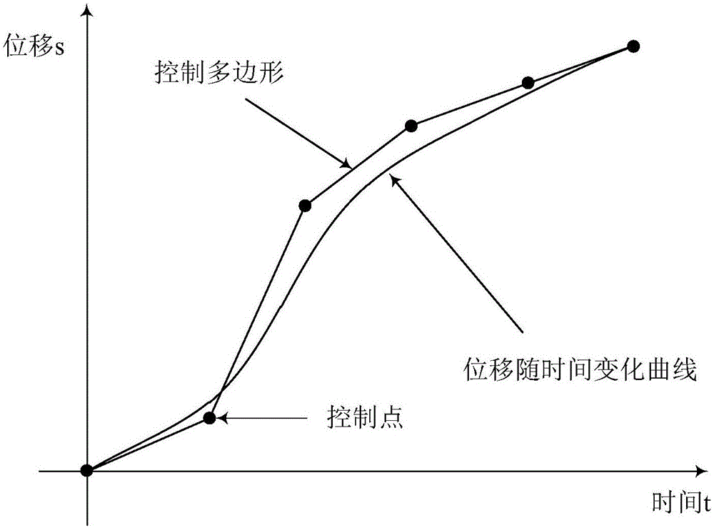
[0019] In the embodiment of the present invention, the planning curve of time t and displacement s adopts spline curve, such as figure 1 As shown, according to the change curve 101 of the displacement with time, the control polygon 102 including the control point 103 can be drawn, figure 1 Take six control points 103 as an example. Specif...


PUM


Abstract

The invention relates to the technical field of robot control, and discloses a speed planning method. The speed planning method comprises the following steps: the S speed planning is performed for all shafts of a multi-shaft mechanism according to a first restraint condition, wherein the first restraint condition includes a motion path, speeds of a starting point and an ending point, accelerations of the starting point and the ending point, an operation speed, a maximum operation speed, a maximum acceleration and a maximum accelerated acceleration; the shaft with the longest time is selected from the planning result as a reference shaft; and according to a second restraint condition, with three B splines as planning curves, the speed planning with given time is renewedly performed for the rest shafts, wherein the second restraint condition includes all restraint conditions besides the operation speed in the first restraint condition, and total operation time of the reference shaft. The method can be used for synchronizing all joint shafts of a robot, also can be used for synchronizing positions and gestures, can solve the synchronizing problem with starting and ending speeds not as zero, and is lower in calculated amount and higher in timeliness.

Description

technical field [0001] The invention relates to the technical field of robot control, in particular to a speed planning method. Background technique [0002] Robots are multi-axis mechanisms. When performing a task, the axes of the robot often need to be synchronized, that is, to reach the end point at the same time. In order to achieve synchronization, speed planning is often performed on all axes according to their respective characteristics and system requirements, and then the one with the longest time is selected as the reference axis, and other axes are synchronized according to the reference axis. There are two common methods for robot synchronization: (1) synchronization method based on displacement ratio, (2) S-shaped velocity planning method at a given time. [0003] In the process of realizing the present invention, the inventor found that there are at least the following problems in the prior art: the synchronization method based on the displacement ratio can o...

Claims


Application Information

Patent Timeline
IPC IPC(8): B25J9/16
CPCB25J9/1628B25J9/1656B25J9/1664
Inventor 王效杰邓洪洁田贺明
Owner SHANGHAI STEP ELECTRIC
Why Eureka
Try Eureka