
Brake pump pressure releasing cover feeding machine

A brake pump and pressure relief technology, which is applied to conveyors, conveyor objects, transportation and packaging, etc., can solve problems such as low work efficiency and complex structure, and achieve the effect of improving work efficiency

Inactive Publication Date: 2017-05-24
苏州迈邻物业管理有限公司
View PDF0 Cites 0 Cited by
  • Summary
  • Abstract
  • Description
  • Claims
  • Application Information

AI Technical Summary

Problems solved by technology

[0002] The brake pump is composed of parts such as a pressure relief cover, a sealing ring, and a sealing sleeve. During the feeding process of the pressure relief cover, a brake pump pressure relief cover feeder is required. The existing brake pump pressure relief cover feeder The structure is complex and requires manual work, which makes the work efficiency low. In view of this, it is necessary to improve the existing brake pump pressure relief cover feeder

Method used


Image

  • Brake pump pressure releasing cover feeding machine
  • Brake pump pressure releasing cover feeding machine
  • Brake pump pressure releasing cover feeding machine

Examples


Embodiment Construction

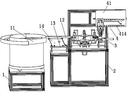
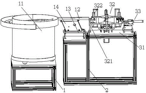
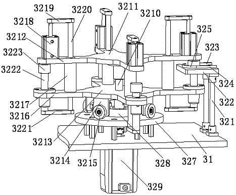
[0027] The preferred embodiments of the present invention will be described in detail below in conjunction with the accompanying drawings, so that the advantages and features of the present invention can be more easily understood by those skilled in the art, so as to define the protection scope of the present invention more clearly.

[0028] see Figure 1 to Figure 15 , the embodiment of the present invention includes:

[0029] A brake pump pressure relief cover feeder, the brake pump pressure relief cover feeder includes a vibrating material plate mounting frame 1 and a frame 2 installed on the ground in sequence, the vibrating material plate mounting frame 1 is installed through the vibrating material plate The plate is installed with a vibrating material tray 11, and a pressure relief cover is placed inside the vibrating material tray 11. The discharge port of the vibrating material tray 11 is equipped with a conveying trough 12, and a linear vibrator is installed on the fr...


PUM


Abstract

The invention discloses a brake pump pressure releasing cover feeding machine. The brake pump pressure releasing cover feeding machine comprises a vibration disc installing frame and a rack which are sequentially arranged on the ground. A vibration disc is arranged on the vibration disc installing frame through a vibration disc installing plate. A pressure releasing cover is placed in the vibration disc. A conveying groove is formed in a discharging port of the vibration disc. The part, below the conveying groove, of the rack is provided with a linear vibrator installing base through an installing plate, and the linear vibrator installing base is provided with a linear vibrator. The linear vibrator is fixed to the lower plane of the conveying groove. The part, on the outer side of a discharging port of the conveying groove, of the rack is provided with a feeding mechanism. The part, on one side of the feeding mechanism, of the rack is provided with a discharging mechanism. By means of the above manner, full-automatic operation is achieved in the pressure releasing cover feeding process, manual pressure releasing cover feeding is replaced, continuous and automatic feeding can be achieved, and the work efficiency is improved.

Description

technical field [0001] The invention relates to the field of mechanical automation, in particular to a brake pump pressure relief cover feeding machine. Background technique [0002] The brake pump is composed of pressure relief cover, sealing ring, sealing sleeve and other parts. During the loading process of the pressure relief cover, a brake pump pressure relief cover feeder is needed. The existing brake pump pressure relief cover feeder The structure is complex and requires manual work, which makes the work efficiency low. In view of this, it is necessary to improve the existing feeder for the brake pump pressure relief cover. Contents of the invention [0003] The main technical problem to be solved by the present invention is to provide a brake pump pressure relief cover feeding machine, which is fully automatic in the process of loading the pressure relief cover, instead of manual loading of the pressure relief cover, and can continuously and automatically load ma...

Claims


Application Information

Patent Timeline
Patent Type & Authority Applications(China)
IPC IPC(8): B65G47/14
CPCB65G47/1421B65G2201/02
Inventor 李华
Owner 苏州迈邻物业管理有限公司
Learn More