Machining automatic conveying device

An automatic conveying device and machining technology, applied in the field of machining, can solve the problems of low efficiency of manual feeding and waste of labor, and achieve the effect of novel design and high degree of automation

Active Publication Date: 2019-11-26
XIAN UNIV OF POSTS & TELECOMM
View PDF8 Cites 0 Cited by
  • Summary
  • Abstract
  • Description
  • Claims
  • Application Information

AI Technical Summary

Problems solved by technology

[0003] In the process of processing, the conveying efficiency of processing raw materials determines the working efficiency to a certain extent. Most of the existing methods of conveying cylindrical parts use manual feeding, which is low in efficiency and wastes labor, and some of them use a single conveying method. However, under the premise of conveying by the conveyor belt, it is still necessary to manually place the raw materials on the conveyor belt

Method used


Image

  • Machining automatic conveying device
  • Machining automatic conveying device
  • Machining automatic conveying device

Examples


Embodiment 1

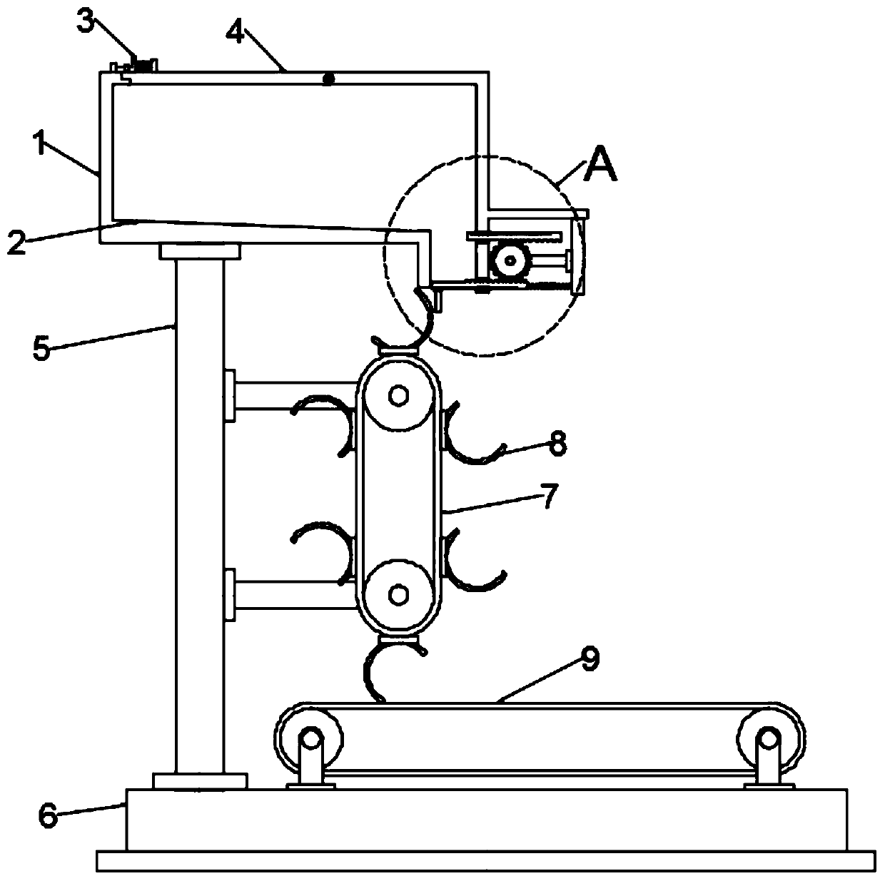
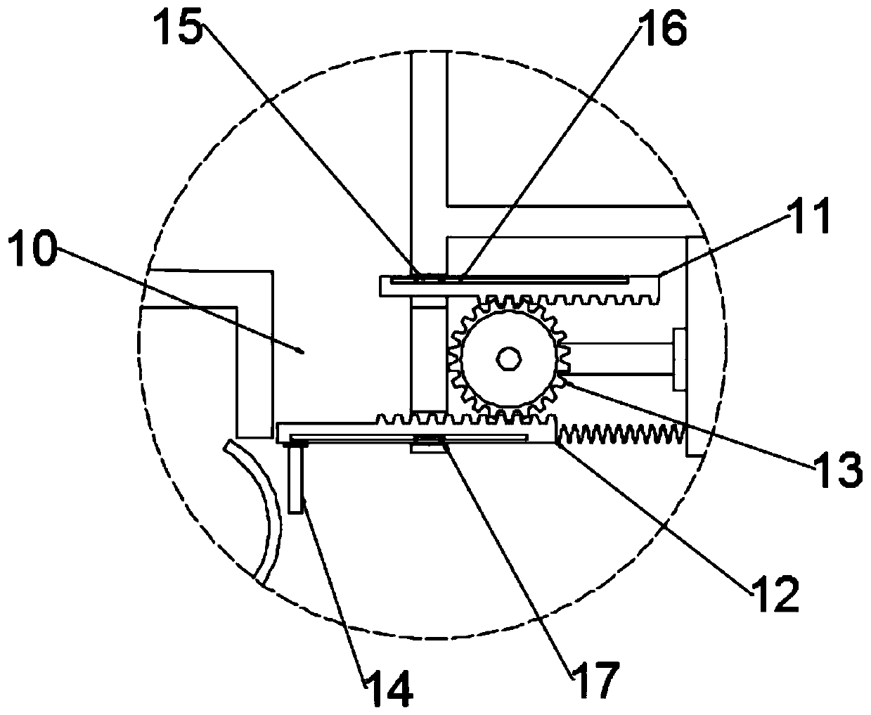
[0024] see Figure 1~3 , in an embodiment of the present invention, a mechanical processing automatic conveying device includes a placement cavity 1; the placement cavity 1 is fixed on the base 6 through a bracket 5, a buffer cavity 10 is provided at the lower end of the placement cavity 1, and The upper and lower ends of the buffer chamber 10 are provided with an upper rack plate 11 and a lower rack plate 12 with opposite moving directions, and a conveying chain assembly 7 mounted on a bracket 5 is arranged below the placement chamber 1, and the conveying chain assembly 7, etc. A plurality of arc-shaped claws 8 are installed at a distance. When one of the arc-shaped claws 8 moves to the upper end of the conveyor chain assembly 7, the arc-shaped claws 8 abut against the driving plate 14 fixed on the lower rack plate 12, and in the arc When the claw 8 continues to move, the drive plate 14 drives the lower rack plate 12 to open, and the cylindrical part falls into the arc claw 8...

Embodiment 2

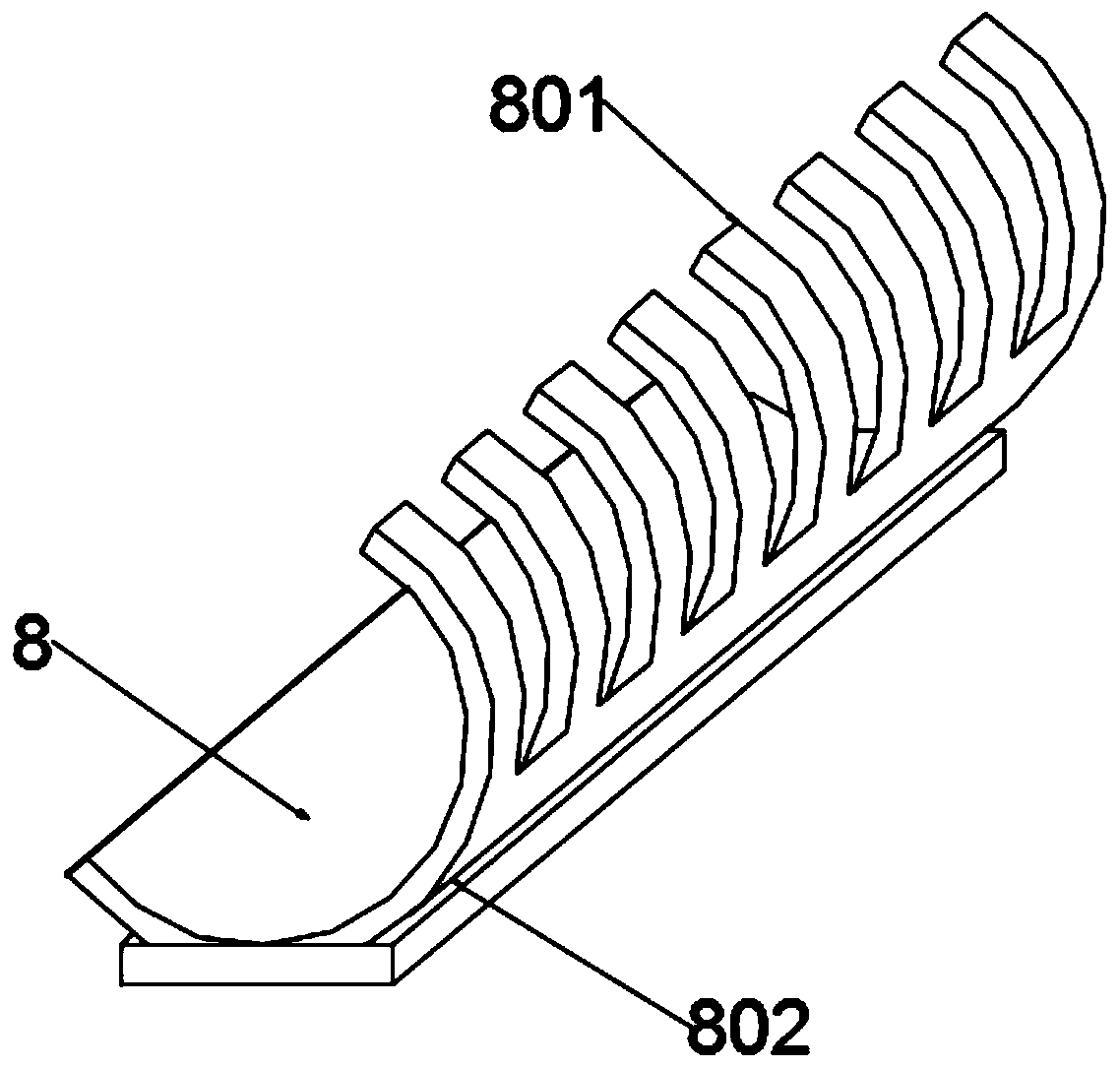
[0033] see Figure 4 and 5 , during the specific implementation process of the present invention, another embodiment is proposed to perfect the present application. Specifically, the conveyor belt 9 is provided with a plurality of convex lines 18, and the convex lines 18 are composed of a mounting plate 1802 and a raised block 1801 Composition, the protruding blocks 1801 are provided with a plurality of them and fixed on the mounting plate 1802 equidistantly. When the cylindrical piece falls onto the conveyor belt 9, the position is limited by the convex strip 18 to prevent the cylindrical piece from rolling freely.


PUM


Abstract

The invention relates to the correlation technical field of machining, in particular to a machining automatic conveying device. The machining automatic conveying device comprises a containing cavity.The containing cavity is fixed to a base through a support, a buffer cavity is formed in one side of the lower end of the containing cavity, an upper rack plate and a lower rack plate are arranged atthe upper end and the lower end of the buffer cavity, the motion directions of the upper rack plate and the lower rack plate are opposite, a conveying chain assembly mounted on the support is arrangedbelow the containing cavity, and multiple arc-shaped jaws are mounted on the conveying chain assembly at equal intervals. The design is novel, when the arranged arc-shaped jaws move to the upper endof the conveying chain assembly, the arc-shaped jaws abut against a drive plate fixed to the lower rack plate, when the arc-shaped jaws continuously move, the drive plate drives the lower rack plate to be opened, a columnar part falls into the arc-shaped jaws, under the blocking effect of the upper rack plate, the other columnar parts are prevented from falling out, thus, continuous automatic feeding is achieved, and the automation degree is high.

Description

technical field [0001] The invention relates to the technical field related to mechanical processing, in particular to an automatic conveying device for mechanical processing. Background technique [0002] Machining refers to the process of changing the shape or performance of a workpiece through a mechanical device. According to the difference in processing method, it can be divided into cutting processing and pressure processing. [0003] In the process of processing, the conveying efficiency of processing raw materials determines the working efficiency to a certain extent. Most of the existing methods of conveying cylindrical parts use manual feeding, which is low in efficiency and wastes labor, and some of them use a single conveying method. However, under the premise of conveying by the conveyor belt, it is still necessary to manually place the raw materials on the conveyor belt. Contents of the invention [0004] The object of the present invention is to provide a ...

Claims


Application Information

Patent Timeline
Patent Type & Authority Applications(China)
IPC IPC(8): B23Q7/00
CPCB23Q7/00
Inventor 王敏娟杨春杰郑转平
Owner XIAN UNIV OF POSTS & TELECOMM
Why Eureka
Try Eureka