
Fine wire guiding device

A guiding device and thin wire technology, which is applied in the directions of transportation and packaging, delivery of filamentous materials, thin material processing, etc., can solve the problems of wire resistance influence, large conveying resistance, and influence on wire conveying process, etc. Effect of large wire conveying force

Inactive Publication Date: 2017-05-24
WUXI VIGOROUS ELECTRIC
View PDF5 Cites 25 Cited by
  • Summary
  • Abstract
  • Description
  • Claims
  • Application Information

AI Technical Summary

Problems solved by technology

[0002] Wire is an essential component in electrical equipment. Generally, the wire is wrapped with an insulating plastic layer on the outside of the inner copper core. In the wire production process, the inner copper core is processed separately first, and then passed through another process. The insulating plastic layer is processed outside the copper core. The general insulating plastic layer is formed by cooling and solidifying the molten hot material. The outer insulating plastic layer is formed and needs to enter the dry powder machine station after passing through the spark machine. During the intermediate transmission process, The wire passing through the dry powder machine is easily affected by resistance, which leads to greater resistance of the wire during subsequent conveyance than between the previous runners, which affects the overall wire conveying process

Method used


Image

  • Fine wire guiding device
  • Fine wire guiding device

Examples


Embodiment Construction

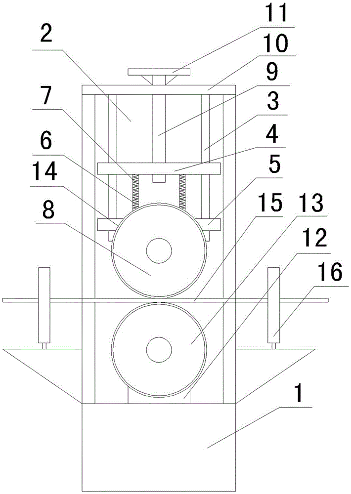
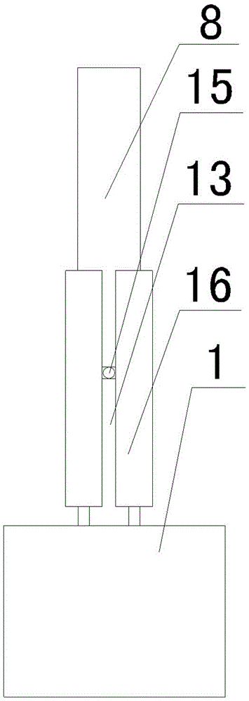
[0009] See figure 1 , figure 2 As shown, a thin wire guiding device includes a base 1, a groove space 2 is opened on the base 1, vertical guide rods 3 are installed on both sides of the upper end of the groove space 2, and a mobile seat is set on the vertical guide rod 3. The moving seat includes an upper plate 4 and a lower plate 5 with guide holes matched with the vertical guide rod 3 and an intermediate link 6 connecting the upper plate 4 and the lower plate 5. The intermediate link 6 is covered with a spring 7, and the effect of the spring is It can make the upper plate 4 and the lower plate 5 be supported by a certain elasticity, which can offset some shaking caused by the rotation of the upper guide wheel 8 on the lower plate 5. There is a threaded hole in the middle of the upper plate 4, and a screw rod is installed in the threaded hole. 9. The upper end of the screw 9 is a polished rod and runs through the top plate 10 of the base 1. A rotating handle 11 is installed...


PUM


Abstract

The invention relates to the technical field of wire processing, and in particular to a fine wire guiding device. The fine wire guiding device can realize guided conveyance of a fine wire, enlarge the conveying fore of the wire, and ensure sequential and stable conveyance. A slot space is formed in a base, vertical guide rods are mounted on two sides of the upper end in the slot space, an upper plate, a lower plate and intermediate connecting rods which connect the upper plate with the lower plate sleeve the vertical guide rods, a spring sleeves each intermediate connecting rod, a threaded hole is formed in the middle of the upper plate, a screw is mounted in the threaded hole, an upper guiding base is mounted at the lower end of the lower plate, an upper motor is mounted on the upper guiding base, and an upper guiding wheel is mounted on an output shaft of the upper motor; at the lower end of the upper guiding base, a lower guiding base is mounted on the base, a lower motor is mounted on the lower guiding base, a lower guiding wheel corresponding to the upper guiding wheel is mounted on an output shaft of the lower motor, the upper motor and the lower motor are synchronously driven, and the upper guiding wheel and the lower guiding wheel are each sleeved with an annular belt.

Description

technical field [0001] The invention relates to the technical field of wire processing, in particular to a thin wire guiding device. Background technique [0002] Wire is an essential component in electrical equipment. Generally, the wire is wrapped with an insulating plastic layer on the outside of the inner copper core. In the wire production process, the inner copper core is processed separately first, and then passed through another process. The insulating plastic layer is processed outside the copper core. The general insulating plastic layer is formed by cooling and solidifying the molten hot material. The outer insulating plastic layer is formed and needs to enter the dry powder machine station after passing through the spark machine. During the intermediate transmission process, The wire passing through the dry powder machine is easily affected by the resistance, which causes the resistance of the wire to be greater than that between the previous runners during the s...

Claims


Application Information

Patent Timeline
Patent Type & Authority Applications(China)
IPC IPC(8): B65H57/14B65H51/10
CPCB65H57/14B65H51/10B65H2404/14B65H2701/341
Inventor 高士红
Owner WUXI VIGOROUS ELECTRIC
Learn More