Eureka AIR delivers breakthrough ideas for toughest innovation challenges, trusted by R&D personnel around the world.

Hydraulic control system of bulldozer blade and control method

A technology of a hydraulic control system and a control method, which is applied to earth movers/excavators, construction, etc., and can solve problems such as low service life of blade cylinders and high difficulty in arranging internal parts of the machine

Active Publication Date: 2017-05-24
SHANTUI CONSTR MASCH CO LTD
View PDF5 Cites 2 Cited by
  • Summary
  • Abstract
  • Description
  • Claims
  • Application Information

AI Technical Summary

Problems solved by technology

[0004] The purpose of the present invention is to provide a bulldozer blade hydraulic control system, which solves the problems of low service life of the blade cylinder and high difficulty in arranging the internal parts of the whole machine

Method used


Image

  • Hydraulic control system of bulldozer blade and control method
  • Hydraulic control system of bulldozer blade and control method
  • Hydraulic control system of bulldozer blade and control method

Examples


Embodiment Construction

[0033] The technical solutions of the present invention are further described below with reference to the accompanying drawings and through specific embodiments.

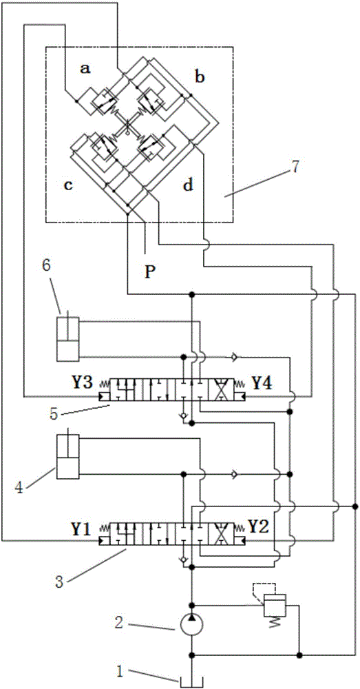
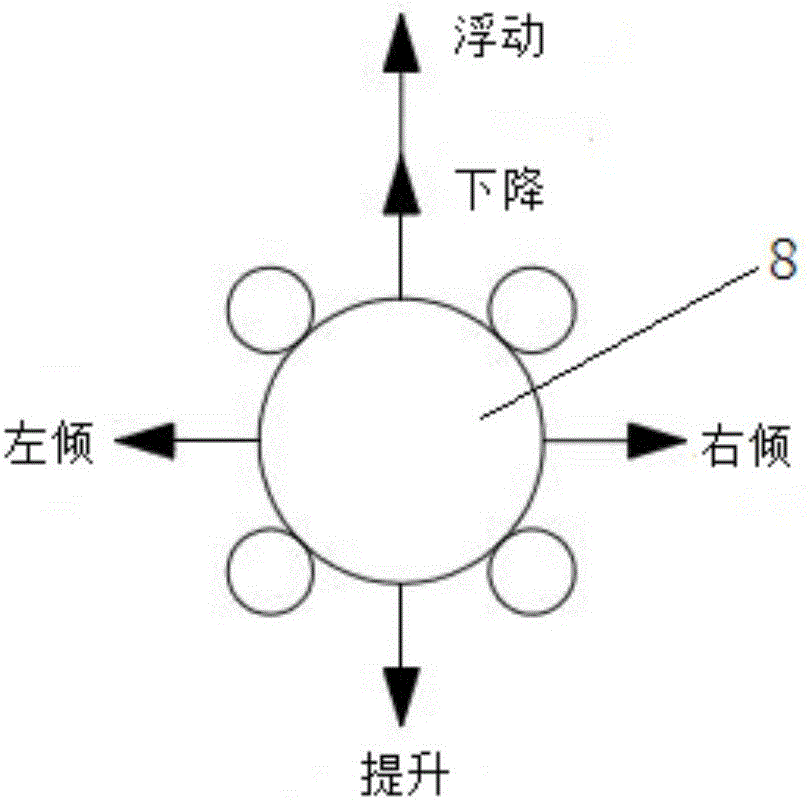
[0034] like Figure 2-3 As shown, the present invention provides a hydraulic control system for a bulldozer blade, including a fuel tank 1 , a hydraulic pump 2 , a right lift valve 3 , a right lift cylinder 4 , a left lift valve 5 , a left lift cylinder 6 and a pilot control valve 7 .

[0035] The right poppet valve 3 and the left poppet valve 5 are both four-position six-way valves. The oil in the oil tank 1 is connected to the oil inlets of the right poppet valve 3 and the left poppet valve 5 after passing through the hydraulic pump 2, and the right poppet valve 3 is connected with the oil inlet. The left lift valve 5 is arranged in parallel, the oil outlet of the right lift valve 3 is connected with the right lift cylinder 4 and the oil tank 1, and the oil outlet of the left lift valve 5 is connected with the lef...


PUM


Abstract

The invention relates to the technical field of bulldozers, particularly to a hydraulic control system of a bulldozer blade and a control method. The hydraulic control system comprises a pilot control valve, a left lift valve, a left lift cylinder, a right lift valve and a right lift cylinder, wherein the pilot control valve controls the left lift valve and the right lift valve; and the left lift valve and the right lift valve respectively control the left lift cylinder and the right lift cylinder. According to the hydraulic control system, through operation of a handle, oil is introduced or drained at pilot control ends on the two sides of the left lift valve and the right lift valve, the left lift cylinder and the right lift cylinder are in the stretched or compressed state, and lifting, falling and floating of the blade are achieved; or one of the left lift cylinder and the right lift cylinder is in the stretched state and the other of the left lift cylinder and the right lift cylinder is in the compressed state, inclination action of the blade is achieved, when a traditional blade is inclined, in-cylinder abnormal high pressure caused by passive stretching or compression of the lift cylinders of the blade is avoided, and the service life of the lift cylinders is effectively prolonged; and inclined cylinders and corresponding pipelines are eliminated, so that the structure of the integral machine is simplified, layout is more simple, and manufacturing cost of the integral machine is reduced.

Description

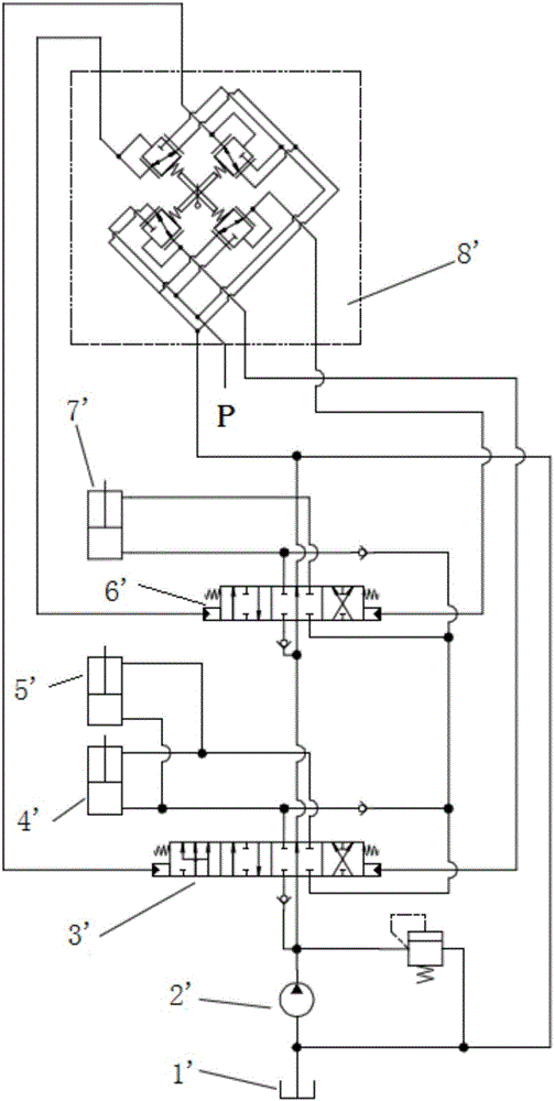
technical field [0001] The invention relates to the technical field of bulldozers, in particular to a hydraulic control system and control method of a bulldozer blade. Background technique [0002] figure 1 A hydraulic control system for a bulldozer blade provided by the prior art is shown, including a blade lifting system and a blade tilting system. The blade lifting system includes a lifting valve 3', a lifting cylinder I4' and a lifting cylinder II5', and the blade The tilting system includes a tilting valve 6' and a tilting cylinder 7', in addition to a fuel tank 1', a hydraulic pump 2' and a pilot control valve 8'. The pilot control valve 8' is provided with a control handle, which simultaneously controls the lift Valve 3' and tilt valve 6', thereby controlling lift cylinder I4', lift cylinder II5' and tilt cylinder 7'. The blade lifting system consists of a blade lifting valve and two left and right blade lifting cylinders. The lifting valve 3' controls the left and ...

Claims


Application Information

Patent Timeline
IPC IPC(8): E02F3/85
CPCE02F3/844
Inventor 宋金宝田从丰金轲赵建军
Owner SHANTUI CONSTR MASCH CO LTD
Why Eureka
Eureka Blog
Learn More