Channel steel end plate joint for square steel string

A technology for connecting nodes and square steel pipes, applied in the direction of architecture and building structure, can solve the problems of affecting the beauty of the building, complicated construction, large welding workload, etc., and achieve high construction efficiency, economic and social benefits, and on-site workload. Less, improve the effect of construction efficiency

Inactive Publication Date: 2017-05-24
YANSHAN UNIV
View PDF10 Cites 3 Cited by
  • Summary
  • Abstract
  • Description
  • Claims
  • Application Information

AI Technical Summary

Problems solved by technology

For inner diaphragm joints, the last welding seam of the inner diaphragm is welded in a closed column, which needs to be completed by electroslag welding. The construction is complicated and the cost is high. At the same time, if holes are opened on the diaphragm to pour concrete, the The size of the hole is affected by the size of the section, and the pouring of concrete in the steel pipe is difficult
The clapboard through joint needs to disconnect the steel pipe column at the joint, the structure is complex, the welding workload is large, and there are concrete pouring problems like the inner clapboard joint, and our country recommends the column through joint, so the clapboard through Nodes are rarely used in my country
The construction of the outer diaphragm joint is simple and not limited by the section size of the steel pipe, but the amount of steel used is relatively large, and the outer diaphragm makes the corner of the joint protrude, which affects the appearance of the building

Method used


Image

  • Channel steel end plate joint for square steel string
  • Channel steel end plate joint for square steel string
  • Channel steel end plate joint for square steel string

Examples


Embodiment 1

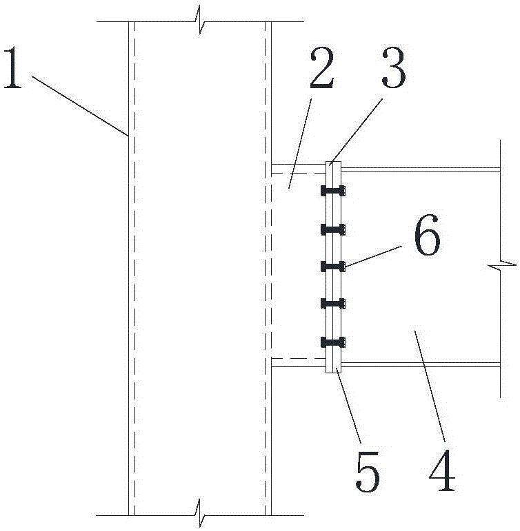
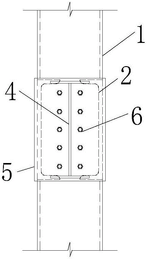
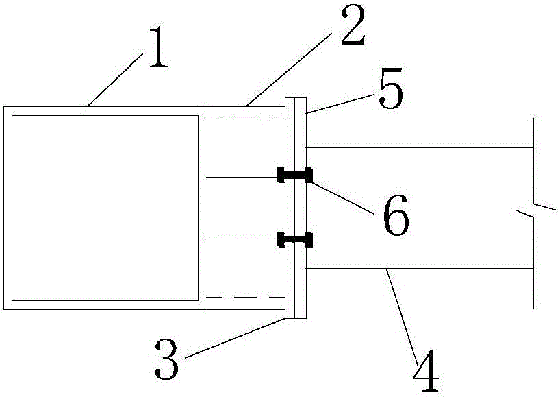
[0019] in figure 1 , figure 2 with image 3 The channel steel end plate connection node of the square steel pipe column shown in the schematic diagram, the two equal-length channel steel sections 2 opposite to the left and right openings, one end of which is vertically fixed on the flange of the square steel pipe column 1, and the other end is fixed with two The node end plates 3 covered by the channel steel ends are all located in the flanges of the square steel pipe columns. The node end plate is provided with two rows of symmetrical bolt holes on two straight lines on both sides of the vertical center line. In addition, a beam end plate 5 covering the end of the I-beam and having the same size as the node end plate is fixed at the end of the I-steel beam 4 to be connected to the square steel pipe column. The beam end plate is provided with bolt holes corresponding to the node end plate, and each pair of bolt holes corresponding to the beam end plate and the node end plate i...

Embodiment 2

[0021] in Figure 4 , Figure 5 with Image 6 In the schematic diagram of the channel steel end plate connection node of the square steel pipe column shown, the two equal-length channel steel sections 2 with the upper and lower openings are fixed vertically on the flange of the square steel pipe column 1, and the other end is fixed with two The node end plates 3 covered by the channel steel ends are all located in the flanges of the square steel pipe columns. The node end plate is provided with two rows of symmetrical bolt holes on two straight lines on both sides of the vertical center line. In addition, a beam end plate 5 covering the end of the I-beam and having the same size as the node end plate is fixed at the end of the I-steel beam 4 to be connected to the square steel pipe column. The beam end plate is provided with bolt holes corresponding to the node end plate, and each pair of bolt holes corresponding to the beam end plate and the node end plate is provided with a ...


PUM


Abstract

A channel steel end plate joint for a square steel string is mainly characterized in that one ends of two equal-length channel steel segments with opposite openings are perpendicularly fixed to a flange of the square steel string, a joint end plate covering the two channel steel segments is fixed to the other ends, the top ends of the channel steel segments placed vertically or horizontally are positioned in the flange of the square steel string, the joint end plate is provided with a plurality of bolt holes, a beam end plate covering an end of an I-beam is additionally fixed to the end of the I-beam to be connected to the square steel string, the beam end plate is provided with bolt holes corresponding to the joint end plate, and the corresponding bolt holes in one pair in the beam end plate and the joint end plate are each provided with a high-strength bolt inside for fixing the two plates together. The channel steel end plate joint is simple in structure, the construction problem due to the welding of a partition in a square steel tube is solved, and the casting of concrete in the square steel tube is unaffected; the anti-seismic design rules of 'strong joints and weak members'are easy to implement, and the anti-seismic performance is good; the channel steel end plate joint has high construction efficiency and great economic and social benefits.

Description

Technical field [0001] The invention relates to a connection mode of a building steel structure beam and a column. Background technique [0002] Currently, there are three main ways to connect square steel pipe columns and steel beams: inner diaphragm type, diaphragm through type and outer diaphragm type. For the inner diaphragm type node, the last weld of the inner diaphragm is welded in the closed column, which needs to be completed by electroslag welding, which is complicated and expensive. At the same time, if a hole is opened on the diaphragm for concrete pouring, open The size of the hole is affected by the size of the cross section, and the pouring of the concrete in the steel tube brings difficulties. Diaphragm through-type joints require the steel pipe column to be disconnected at the node. The structure is complicated and the welding workload is relatively large. The concrete pouring problem is the same as that of the inner diaphragm-type joint. And my country recommen...

Claims


Application Information

Patent Timeline
Patent Type & Authority Applications(China)
IPC IPC(8): E04B1/24E04B1/58
CPCE04B1/2403E04B1/5812E04B1/5831E04B2001/2418
Inventor 王兆强齐红丽
Owner YANSHAN UNIV
Why Eureka
Try Eureka