LED street lamp capable of achieving high solar energy utilization ratio

A technology of LED street light and utilization rate, applied in the direction of energy-saving lighting, circuit layout, components of lighting devices, etc., can solve the problems of low utilization rate of solar energy conversion, single fixing method of solar LED street light, complicated structure, etc., to improve conversion and utilization. efficiency, improved convenience, and the effect of easy operation

Active Publication Date: 2017-05-24
厦门久贤新能源科技有限公司
View PDF4 Cites 6 Cited by
  • Summary
  • Abstract
  • Description
  • Claims
  • Application Information

AI Technical Summary

Problems solved by technology

Solar street lamps must use solar cell components to provide electrical energy. For different regions and seasons, the installation inclination and azimuth angles of solar cell components are different. Traditional solar LED street lamps have a single fixing method, complex structure and limited adjustment angle. Therefore, Can not get sufficient lighting effect, so it can not fully convert light energy, resulting in low conversion utilization rate of solar energy

Method used


Image

  • LED street lamp capable of achieving high solar energy utilization ratio
  • LED street lamp capable of achieving high solar energy utilization ratio
  • LED street lamp capable of achieving high solar energy utilization ratio

Examples


Embodiment Construction

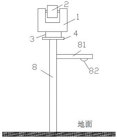
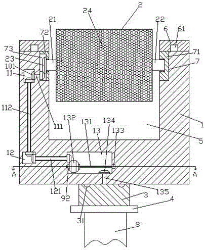
[0021] Such as Figure 1-Figure 5 As shown, an LED street lamp with high solar energy utilization rate of the present invention includes an assembly frame 1 with an assembly groove 5 on the inner top and an assembly seat 3 that is rotationally connected to the bottom of the assembly frame 1. The assembly groove 5 An assembly board 2 is provided inside, and a solar photovoltaic panel 24 is provided on the front end of the assembly board 2, and a first steering shaft 21 and a second steering shaft 22 are respectively provided on the left and right sides of the assembly board 2, and the first steering shaft 21 A first sliding block 72 is connected to the tail end of the left side by rotation and fitting, and a slot 73 is arranged in the first sliding block 72, and a first sliding block fixedly connected with the first steering shaft 21 is arranged in the slot 73 . Three gears 23, the tail end on the right side of the second steering shaft 22 is rotatably connected with a second s...


PUM


Abstract

The invention discloses an LED street lamp capable of achieving the high solar energy utilization ratio. The LED street lamp comprises assembling frames and assembling seats, assembling grooves are formed in the tops of the assembling frames, and the bottoms of the assembling frames are rotatably connected with the assembling seats in a matched mode; assembling plates are installed in the assembling grooves, solar-energy photovoltaic plates are installed on the front end faces of the assembling plates, and first steering shafts and second steering shafts are installed on the left sides and the right sides of the assembling plates correspondingly; first sliding blocks are rotatably connected with the tail ends of the left sides of the first steering shafts in a matched mode, and grooves are formed in the first sliding blocks; third gears being fixedly connected with the first steering shafts are installed in the grooves, second sliding blocks are rotatably connected with the tail ends of the right sides of the second steering shafts in a matched mode, and containing grooves are symmetrically formed in the tops of the inner walls of the left sides and the right sides of the assembling grooves; first cavities are formed in the assembling frames on the sides, being away from the assembling grooves, of the containing grooves on the left sides, second cavities are formed in the assembling frames below the first cavities, and third cavities are formed in the assembling frames on the right sides of the second cavities; and transmission shafts extending leftwards and rightwards are installed in the third cavities, and the right side ends of the transmission shafts are connected with a first motor.

Description

technical field [0001] The invention relates to the technical field of LED street lamps, in particular to an LED street lamp with high utilization rate of solar energy. Background technique [0002] As a clean energy source, solar energy has always been the direction of exploration for human beings to make full use of solar energy. Solar street lights are not affected by power supply, do not consume conventional electric energy, and can be installed on-site as long as the sun resources are sufficient, so they are widely used and concerned. Solar street lights must use solar cell components to provide electrical energy. For different regions and seasons, the installation inclination and azimuth of solar cell components are different. Traditional solar LED street lights have a single fixing method and complex structures. The adjustment angle is limited, so Can not get sufficient lighting effect, so can not fully convert light energy, resulting in low conversion utilization of ...

Claims


Application Information

Patent Timeline
IPC IPC(8): F21S9/03F21V23/00H02S20/30F21W131/103F21Y115/10
CPCF21S8/086F21S9/035F21V23/02F21W2131/103H02S20/30Y02B20/72Y02E10/50
Inventor 俞海东
Owner 厦门久贤新能源科技有限公司
Why Eureka
Try Eureka