Lighthouse lifting device

A technology for lifting devices and lighthouses, applied in the direction of lighting devices, lighting auxiliary devices, lighting device components, etc., can solve problems such as bending deformation of hollow rods, safety impact, uneven force on hollow rods, etc., to achieve uniform force , prolong service life, improve stability and safety

Pending Publication Date: 2017-05-24
ATLAS COPCO WUXI COMPRESSOR
View PDF3 Cites 1 Cited by
  • Summary
  • Abstract
  • Description
  • Claims
  • Application Information

AI Technical Summary

Problems solved by technology

However, in the prior art, the pulleys of the lighthouse lifting device are all arranged on the same side of several hollow rods, so that the several hollow rods that are nested in sequence are subjected to uneven force, which will easily lead to bending deformation of the hollow rods and affect the lifting of the lighthouse. Device life
[0003] In addition, in the prior art, the hollow rods of the lighthouse lifting device mainly rely on the studs at the bottom of the outermost hollow rod and the nuts on the movable frame to achieve axial fixation. When adjusting the height of the lamp, the outermost hollow rod Circumferential stability is far from enough, and the safety of operation is affected
Furthermore, it is impossible to change the lighting direction of the lamp conveniently by turning the outermost hollow rod

Method used


Image

  • Lighthouse lifting device
  • Lighthouse lifting device
  • Lighthouse lifting device

Examples


Embodiment Construction

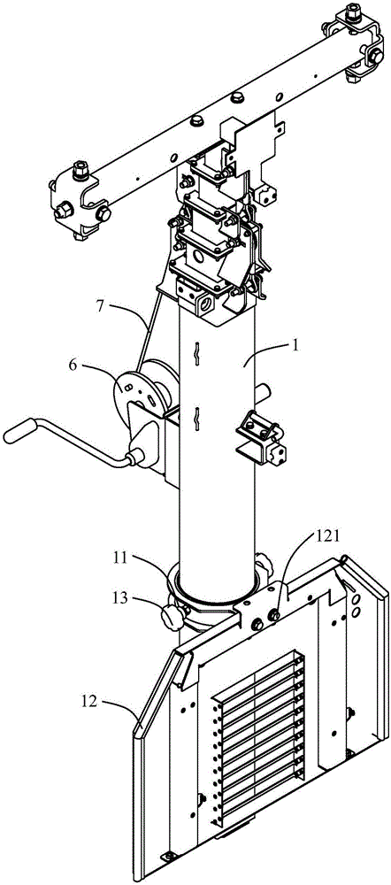
[0031] Below, the structure and working principle of the present invention will be further described in conjunction with the accompanying drawings.

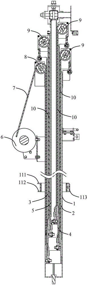
[0032] see figure 1 , figure 2 , the light tower lifting device of the present invention is installed on a movable vehicle frame (not shown in the figure), and the device includes several hollow rods 1, 2, 3, 4, 5 that are sequentially socketed, and the inner hollow rods are placed outside In the cavity of the hollow rods, adjacent hollow rods can slide relative to each other, the outermost hollow rod 1 is fixed on the movable vehicle frame, and the top of the innermost hollow rod 5 is connected to the lamp. The lighthouse lifting device realizes the lifting of the position of the lamp through the relative sliding between the hollow rods.

[0033] Specifically, as figure 2 As shown, the outside of the hollow rod 1 is provided with a driving mechanism, the top is provided with a first pulley 8, and the first pulley 8 is provi...


PUM


Abstract

The invention discloses a lighthouse lifting device which is mounted on a moveable frame and comprises a plurality of hollow rods, wherein the hollow rods are connected in sequence in a sleeved manner; the outermost hollow rod is fixedly arranged on the moveable frame; the innermost hollow rod is connected with a lamp; a driving mechanism is arranged on the outer side of the outermost hollow rod; a first pulley is arranged at the top of the outermost hollow rod; a first steel wire rope is arranged on the first pulley; one end of the first steel wire rope is connected with the driving mechanism; the other end of the steel wire rope crosses the first pulley and is connected with the bottom of a hollow rod adjacent to the outermost hollow rod; a second pulley is arranged at the top of a hollow rod between the outermost hollow rod and the innermost hollow rod; a second steel wire rope is arranged on the second pulley; one end of the second steel wire rope is connected with the top of a hollow rod positioned on the outer side of the hollow rod; the other end of the second steel wire rope crosses the second pulley and is connected with the bottom of a hollow rod positioned on the inner side of the hollow rod; a plurality of second pulleys are respectively distributed on two sides of the hollow rods. By adopting the lighthouse lifting device disclosed by the invention, the hollow rods can be stressed uniformly.

Description

technical field [0001] The invention relates to a light tower lifting device. Background technique [0002] At present, lighthouse lifting devices are used more and more widely, and their structures are also different. One of the lighthouse lifting devices includes several hollow rods that are sequentially socketed. The adjacent hollow rods can slide relative to each other. The pulleys and the hollow rods are connected by wire ropes passing around the pulleys, so as to realize the lifting of each hollow rod and adjust the lamps to a suitable height. However, in the prior art, the pulleys of the lighthouse lifting device are all arranged on the same side of several hollow rods, so that the force of several hollow rods nested in sequence is uneven, which easily leads to bending deformation of the hollow rods and affects the lifting of the lighthouse. The service life of the device. [0003] In addition, in the prior art, the hollow rods of the lighthouse lifting device mainl...

Claims


Application Information

Patent Timeline
IPC IPC(8): F21V21/38F21V21/15F21V23/00
CPCF21V21/15F21V21/38F21V23/00
Inventor 于霞李强陆德忠丛海营
Owner ATLAS COPCO WUXI COMPRESSOR
Why Eureka
Try Eureka