
A positioning and detection method for the center point of the optical path of a polarization-maintaining optical fiber ring

A polarization-maintaining optical fiber ring and polarization-maintaining optical fiber technology are applied in the directions of measuring devices, surveying and navigation, electromagnetic wave reradiation, etc., which can solve the problems of increasing the overall cost of optical fiber gyroscopes and limited measurement accuracy, and achieve improved measurement accuracy, detection and Intercept the effect of easy operation

Active Publication Date: 2019-10-25
HEBEI HUAXING XINRUI COMM TECH
View PDF5 Cites 0 Cited by
  • Summary
  • Abstract
  • Description
  • Claims
  • Application Information

AI Technical Summary

Problems solved by technology

However, the cost of the polarization-maintaining optical fiber ring is mainly concentrated on the polarization-maintaining optical fiber and its winding process. By increasing the length of the wound polarization-maintaining optical fiber, the measurement accuracy of the angular velocity of the optical fiber gyroscope is limited and the overall cost of the optical fiber gyroscope will be significantly increased. For For the fiber optic gyroscope market with huge demand in the future, cost is also an important aspect that must be considered

Method used


Image

  • A positioning and detection method for the center point of the optical path of a polarization-maintaining optical fiber ring
  • A positioning and detection method for the center point of the optical path of a polarization-maintaining optical fiber ring
  • A positioning and detection method for the center point of the optical path of a polarization-maintaining optical fiber ring

Examples


Embodiment Construction

[0029] The technical solutions in the present invention will be clearly and completely described below in conjunction with the accompanying drawings in the present invention.

[0030] The invention provides a method for positioning and detecting the center point of the optical path of a polarization-maintaining optical fiber ring, comprising the following steps:

[0031] Step 1. Pre-locate the center point of the polarization maintaining fiber

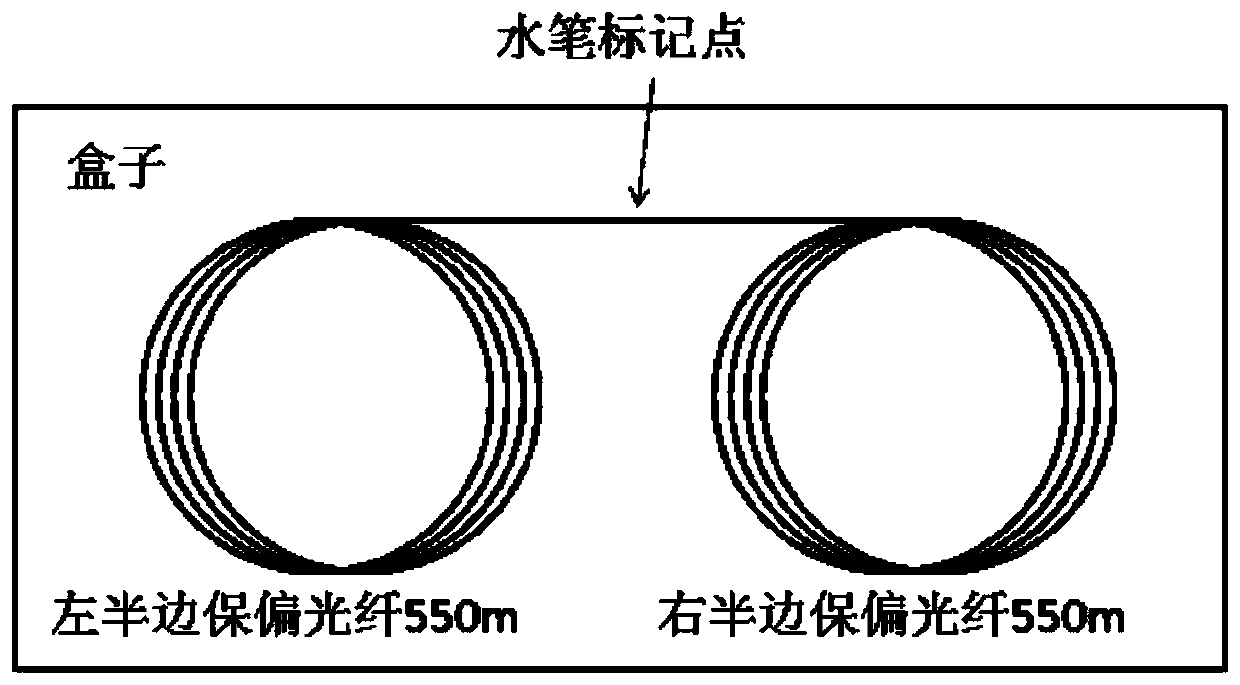
[0032] The length of the polarization-maintaining optical fiber ring used in the fiber optic gyroscope varies from 200m to 5km. The current situation is that the longer the polarization-maintaining optical fiber is used, the higher the accuracy of the fiber optic gyroscope prepared in the later stage. In this embodiment, the preparation of a 1.1 km polarization-maintaining fiber optic gyroscope is taken as an example for illustration. First, a polarization-maintaining fiber with a length of 1.1 km is intercepted. Use a fiber splitter...


PUM


Abstract

The invention provides a positioning and detection method for a central point of an optical distance of a polarization-maintaining optical fiber ring. The positioning and detection method comprises the following steps: engraving an optical fiber grating at a position about nearby the central point of the polarization-maintaining optical fiber ring; winding a polarization-maintaining optical fiber into the polarization-maintaining optical fiber ring; accurately detecting the position of the optical fiber grating in the polarization-maintaining optical fiber ring through an optical frequency domain reflection technology in an optical fiber communication field, and accurately positioning the central point of the optical distance of the polarization-maintaining optical fiber ring; cutting tail fibers at two ends of the polarization-maintaining optical fiber ring and ensuring that length measurement from two back propagation optical paths to the central point of the optical distance of the optical fiber ring is controlled to be mm precision, so as to ensure that a length difference between the tail fibers at the two ends of the cut polarization-maintaining optical fiber ring and the central point of the optical distance of the polarization-maintaining optical fiber ring to be mm precision. By adopting the positioning and detection method provided by the invention, the difficulties in an existing fiber-optic gyroscope technical field that equal lengths of the two ends of the polarization-maintaining optical fiber ring and the central point of the optical distance of a ring body cannot be realized and the like are overcome; meanwhile, the measurement precision of a fiber-optic gyroscope is improved under the condition that the utilization length of the polarization-maintaining optical fiber is not increased (the cost of the polarization-maintaining optical fiber ring is not increased).

Description

technical field [0001] The invention relates to the field of optical fiber sensing, in particular to a method for positioning and detecting the center point of the optical path of a polarization-maintaining optical fiber ring. Background technique [0002] The working principle of the fiber optic gyroscope is based on the Sagnac Effect. The Sagnac effect is a general correlation effect of light propagating in a closed-loop optical path that rotates relative to inertial space, that is, two beams of light with equal characteristics emitted from the same light source in the same closed optical path propagate in opposite directions. Finally converge to the same detection point. If there is a rotation angular velocity relative to the inertial space around the axis perpendicular to the plane where the closed optical path is located, the optical path of the light beam propagating in the forward and reverse directions will be different, resulting in an optical path difference, and ...

Claims


Application Information

Patent Timeline
Patent Type & Authority Patents(China)
IPC IPC(8): G01C25/00G01C19/72G01S17/06
CPCG01C19/721G01C25/005G01S17/06
Inventor 俞婷阎志兵刘永宽
Owner HEBEI HUAXING XINRUI COMM TECH
Learn More