
Glass-plate liquid level meter

A glass plate and liquid level gauge technology, applied in the field of liquid level gauges, can solve the problems of difficulty in accurately observing the scale of the liquid level gauge, damage of the glass plate liquid level gauge, reduction of service life, etc. The effect of improving the age and service life

Inactive Publication Date: 2017-05-24
TIANJIN HUIYUFENG ELECTROMECHANICAL TECH CO LTD
View PDF1 Cites 0 Cited by
  • Summary
  • Abstract
  • Description
  • Claims
  • Application Information

AI Technical Summary

Problems solved by technology

The glass plate liquid level gauge has the advantages of simple structure, intuitive reliability, and durability. It is suitable for directly indicating the liquid level of the medium in various containers such as towers, tanks, tanks, and boxes. It is easy to use and has a wide range of applications in general measurement environments. The structure of the glass plate level gauge is similar, but when using the glass plate level gauge, it is necessary to always pay attention to the pressure at the connection at both ends. The use of overpressure will directly cause damage to the glass plate level gauge, which will increase the cost of use and reduce the service life. Manpower should pay attention to the pressure at all times. In a dark environment, it is difficult to accurately observe the scale of the liquid level gauge, resulting in deviations in readings.

Method used


Image

  • Glass-plate liquid level meter

Examples


Embodiment Construction

[0011] In order to deepen the understanding of the present invention, the present invention will be further described below in conjunction with the accompanying drawings. This embodiment is only used to explain the present invention, and does not constitute a limitation to the protection scope of the present invention.

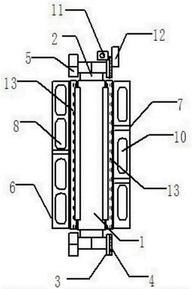
[0012] Such as figure 1 It shows an embodiment of a glass plate liquid level gauge of the present invention, including a body 1, a through-pipe connector 2 is installed at both ends of the body 1, and a flange 3 is installed on one side of the through-pipe connector 2, A sealing ring 4 is arranged in the flange 3, and a pressure sensor 11 is installed on the front side of the flange 3 at the upper end, and a baffle 12 is connected to the pressure sensor 11 through a controller, and the baffle 12 is connected to the At the opening of the flange 3, a blowdown valve 5 is installed on the other side of the through-pipe connector 2, and two glass plates 13 are inst...


PUM


Abstract

The invention discloses a glass-plate liquid level meter. The glass-plate liquid level meter comprises a body. Through-pipe connectors are mounted at two ends of the body respectively. A flange is mounted on one side of each through-pipe connector. A seal ring is arranged in each flange. A pressure sensor is mounted on the front side of the upper flange. A retaining plate is connected with the pressure sensor through a controller, and is connected to an opening of the corresponding flange. A sewage discharge valve is mounted on the other side of each through-pipe connector. Two glass plates are mounted on the front and the rear of the body. A front two-section press plate and a rear three-section press plate are arranged on the outer sides of the glass plates, and are connected with each other through a plurality of fixing pieces. A plurality of first waist-shaped grooves are formed in the front two-section press plate, and a plurality of second waist-shaped grooves are formed in the rear three-section press plate. The first waist-shaped grooves and the second waist-shaped grooves are in staggered arrangement. The glass-plate liquid level meter has the advantages of strong self-protection ability, nonexistence of dead corners in observation, stability in connection and lighting function.

Description

technical field [0001] The invention relates to a liquid level gauge, in particular to a glass plate liquid level gauge. Background technique [0002] The height of the liquid medium in the container is called the liquid level, and the instrument for measuring the liquid level is called a liquid level gauge, and the liquid level gauge is a kind of level instrument. The glass plate liquid level gauge has the advantages of simple structure, intuitive reliability, and durability. It is suitable for directly indicating the liquid level of the medium in various containers such as towers, tanks, tanks, and boxes. It is easy to use and has a wide range of applications in general measurement environments. Ordinary The structure of the glass plate level gauge is similar, but when using the glass plate level gauge, it is necessary to always pay attention to the pressure at the connection at both ends. The use of overpressure will directly cause damage to the glass plate level gauge, w...

Claims


Application Information

Patent Timeline
Patent Type & Authority Applications(China)
IPC IPC(8): G01F23/02
CPCG01F23/02
Inventor 王英杰
Owner TIANJIN HUIYUFENG ELECTROMECHANICAL TECH CO LTD
Learn More