
Calculation method of volumetric water content distribution around injection hole for in-situ leaching of ionic rare earth

A technology of volume moisture content and ionic rare earth, which is applied in the fields of soil material testing, analysis materials, instruments, etc., and can solve the problems of leaching agent residue, insufficient recovery of resources, and increased costs

Active Publication Date: 2018-12-21
JIANGXI UNIV OF SCI & TECH
View PDF3 Cites 0 Cited by
  • Summary
  • Abstract
  • Description
  • Claims
  • Application Information

AI Technical Summary

Problems solved by technology

On the one hand, if the distance between the liquid injection holes is too large, the ore leaching agent cannot infiltrate into a farther area under the condition of a certain liquid injection intensity, which will easily cause a blind area of ​​ore leaching and affect the full recovery of resources.
On the other hand, if the distance between the liquid injection holes is too small, it will not only increase the cost, but also easily cause the phenomenon of channeling. Once channeling occurs, the scope of the leaching blind area will be further increased, and the resource recovery rate will be reduced; in addition, the distance between the liquid injection holes is too small. , it is easy to cause the injection intensity to be too high, and landslides are prone to occur, and the resources in the landslide area are also difficult to recover
At present, the layout of liquid injection holes is mainly based on engineering experience, which has caused a considerable number of mines to recover resources from one-time in-situ leaching. Therefore, repeated in-situ leaching to recover resources not only increases economic costs, but also causes more leaching agents to remain in the mines. mountain

Method used


Image

  • Calculation method of volumetric water content distribution around injection hole for in-situ leaching of ionic rare earth
  • Calculation method of volumetric water content distribution around injection hole for in-situ leaching of ionic rare earth
  • Calculation method of volumetric water content distribution around injection hole for in-situ leaching of ionic rare earth

Examples


Embodiment Construction

[0060] Using the present invention, a leveling site was selected in a certain rare earth mining area in Zudong, Longnan (not publicly tested), and a step was formed by excavation. The soil-water characteristic curve of the ore body was tested with the TEN tensiometer developed by the Nanjing Institute of Soil Science, Chinese Academy of Sciences. The technology tests the initial water content and porosity of the ore body, and uses the FDS-100 moisture sensor to test the volumetric water content at different points during the infiltration process. The implementation process is as follows:

[0061] Step 1: Test the soil-water characteristic curve of the ore body,

[0062] The TEN type tensiometer developed by the Nanjing Institute of Soil Science, Chinese Academy of Sciences was used to test the matrix suction corresponding to the different water content of the ore body, and the test data was fitted by the relationship formula (1), and the saturated volume water content was 47.09% and...


PUM


Abstract

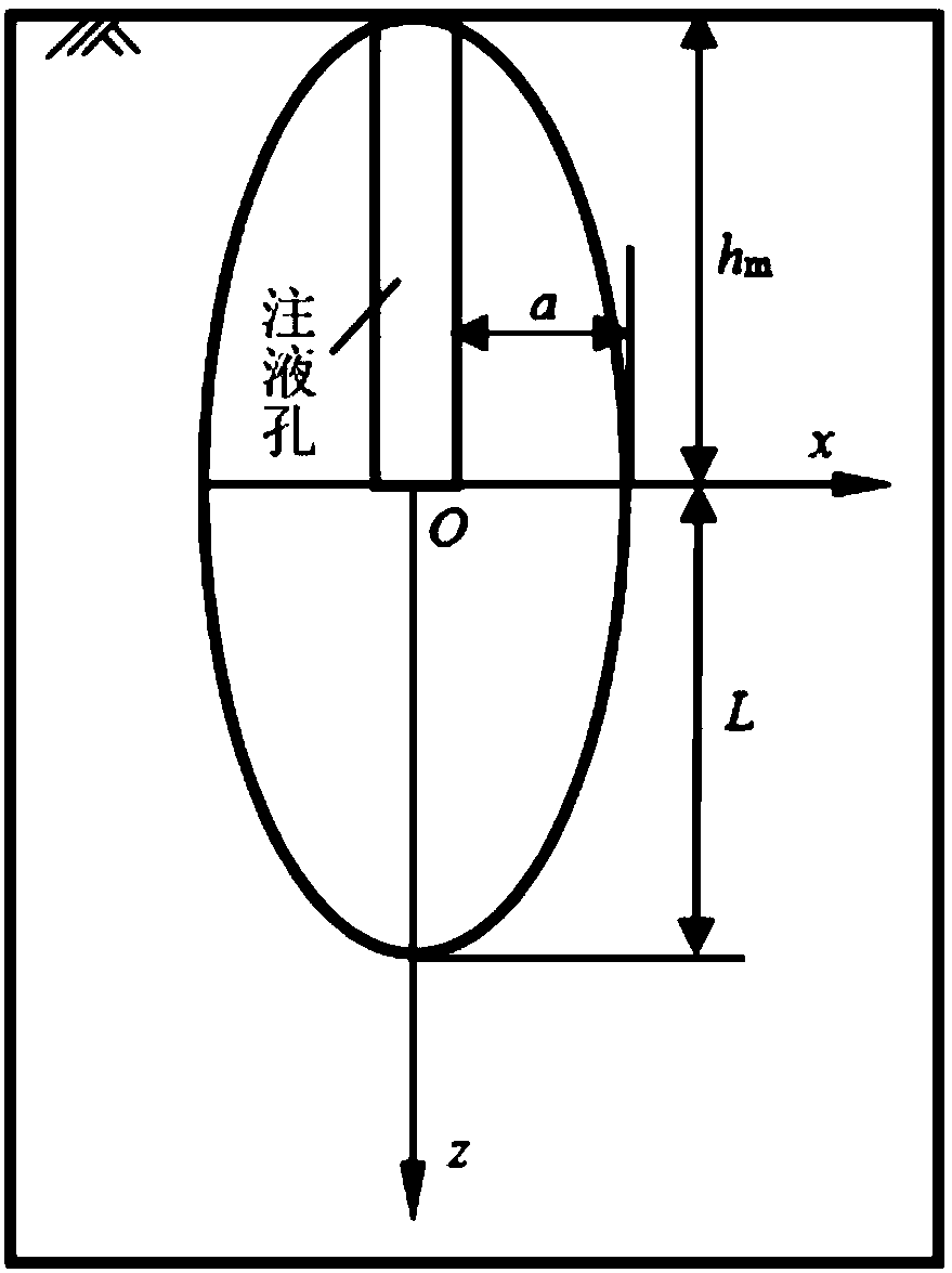
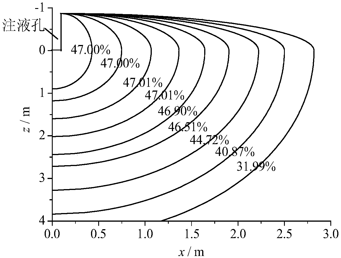
The invention relates to a calculating method of distribution of the volumetric water content around a liquid injection hole for in situ leaching of ion type rare earth, and is applicable to parameter design of a liquid injection hole net for in situ leaching. The calculating method comprises 7 steps: testing a soil-water characteristic curve of an ore body; calculating the specific water capacity of the ore body; calculating an equivalent saturated hydraulic conductivity of the ore body; calculating a hydraulic conductivity of the ore body; calculating the diffusion rate of the ore body; calculating the water content distribution in the perpendicular direction of the center of the bottom of the liquid injection hole; and calculating the distribution of the volumetric water content around the liquid injection hole. According to the calculating method disclosed by the invention, on the basis of testing soil parameters, a built model is used for calculating the distribution of the water content around the liquid injection hole, so as to supply a basis to the parameter design of the liquid injection hole net for the in situ leaching.

Description

Technical field [0001] The invention relates to a calculation method for the volumetric water content distribution around the injection hole of an ionic rare earth leaching ore, and is suitable for the parameter design of an in-situ leaching ore injection hole network. Background technique [0002] The in-situ leaching process has the advantages of high resource recovery rate, green, environmental protection, and strong adaptability. For ionic rare earth resources with very large mineralization areas and very small resources per unit area, the in-situ leaching process is difficult to be used by other processes. The advantage of complete substitution has become the country's vigorously popularized and applied ionic rare earth mining technology. The in-situ leaching process is to arrange liquid injection holes in the area of ​​the rare earth ore body according to certain pore network parameters, and inject the leaching agent solution into the ore body through the liquid injection h...

Claims


Application Information

Patent Timeline
Patent Type & Authority Patents(China)
IPC IPC(8): G01N33/24
CPCG01N33/246
Inventor 龙平王观石胡世丽洪本根罗嗣海
Owner JIANGXI UNIV OF SCI & TECH
Learn More