
Biomass pyrolysis heat supply device and use method thereof

A biomass pyrolysis and heating device technology, applied in the field of biomass pyrolysis heating devices, can solve the problems of waste gas containing a large amount of heat, environmental pollution, waste, etc., achieve scientific and reasonable adjacent spacing, reduce waste, and improve efficiency Effect

Active Publication Date: 2021-12-31
武汉蓝颖新能源有限公司
View PDF12 Cites 0 Cited by
  • Summary
  • Abstract
  • Description
  • Claims
  • Application Information

AI Technical Summary

Problems solved by technology

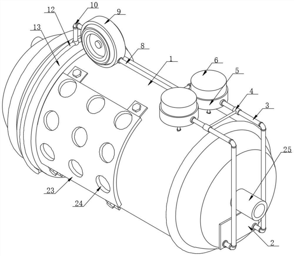
[0005] In order to overcome the above-mentioned defects of the prior art, the present invention provides a biomass pyrolysis heat supply device and its use method. The technical problem to be solved by the present invention is: in the process of using the biomass energy pyrolysis heat supply device, Some exhaust gases are often produced, and the direct discharge of these exhaust gases will not only pollute the environment, but also contain a large amount of heat in the exhaust gas, which will cause waste when discharged directly. Therefore, a biomass energy pyrolysis supply that processes impurities and heat in the exhaust gas is needed The thermal device treats the waste gas generated by the pyrolysis of biomass energy

Method used


Image

  • Biomass pyrolysis heat supply device and use method thereof
  • Biomass pyrolysis heat supply device and use method thereof
  • Biomass pyrolysis heat supply device and use method thereof

Examples


Embodiment 1

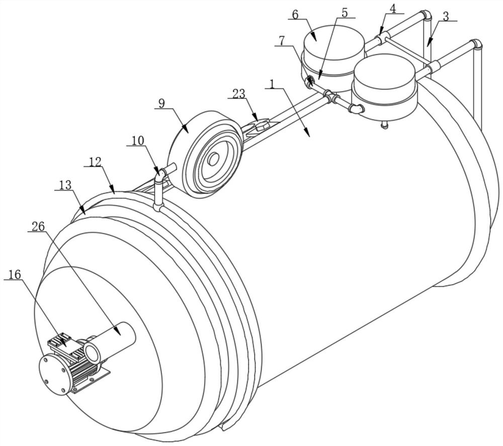
[0030] Such as figure 1 , figure 2 , Figure 4 and Figure 5As shown, the present invention provides a biomass pyrolysis heat supply device, comprising a pyrolysis furnace 1, the right side of the pyrolysis furnace 1 is fixedly connected with a mounting plate 2, and the right side of the mounting plate 2 is connected to two first The left end of conduit 3 is communicated, and two first conduits 3 pass mounting plate 2 and are communicated with the right side of pyrolysis furnace 1, and the other end of two first conduits 3 passes two protective sleeves 5 respectively and two The outer surface of the filter barrel 6 is connected, the protective cover 5 is sleeved on the outer surface of the filter barrel 6, and the outer surfaces of the two filter barrels 6 are connected with the right ends of the two second conduits 7 respectively, and the two second conduits 7 The other end of the same cluster tube 8 is connected with the right end, the left end of the cluster tube 8 is c...

Embodiment 2

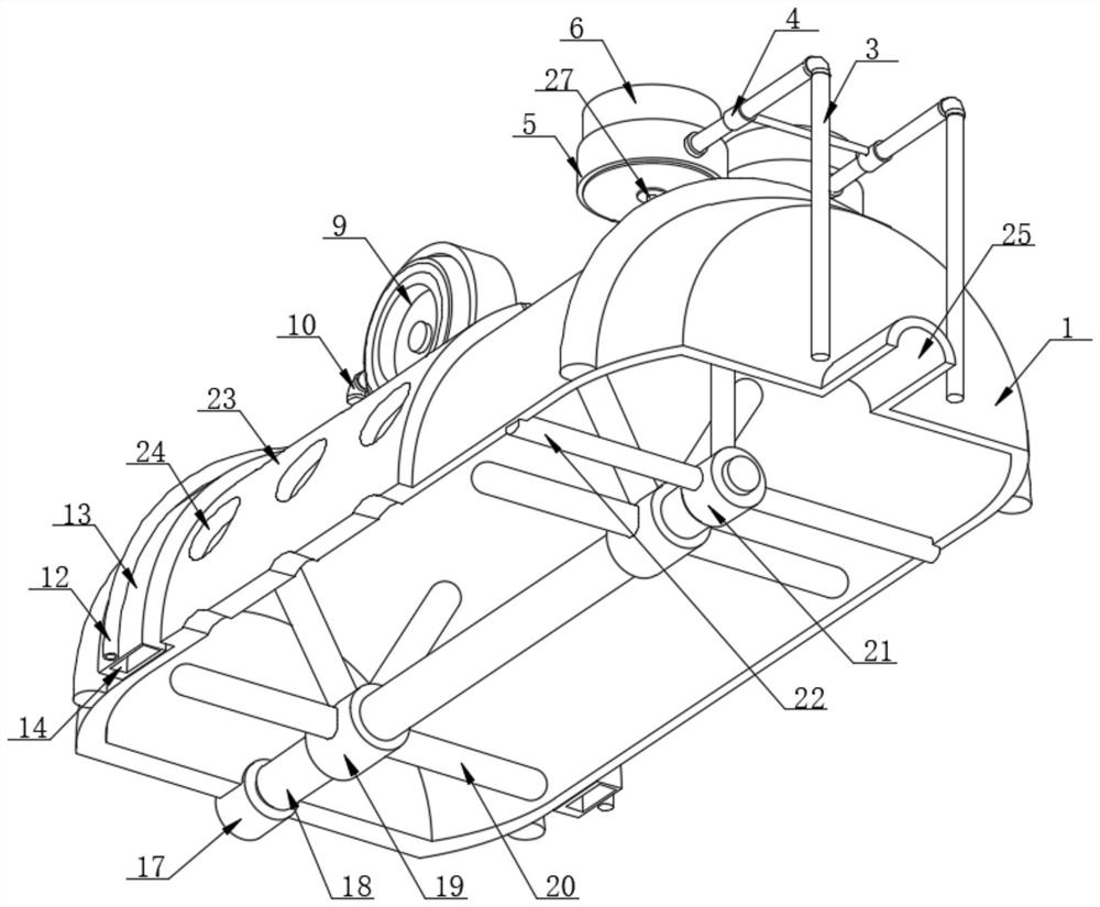
[0037] On the basis of Example 1, as figure 1 , image 3 and Figure 6 As shown, the present invention provides a biomass pyrolysis heat supply device, the left side of the pyrolysis furnace 1 is fixedly connected to the right side of the driving device 16, and the drive shaft on the right side of the driving device 16 is connected to the left end of the rotating device 17 Fixedly connected, the rotating device 17 is clamped on the left side of the pyrolysis furnace 1, the right end of the rotating device 17 is fixedly connected with the left end of the connecting shaft 18, and the outer surface of the connecting shaft 18 is fixedly connected with a stirring shaft 19.

[0038] The outer surface of the stirring shaft 19 is provided with several stirring rods 20, the right end of the connecting shaft 18 is clamped with a positioning frame 21, the outer surface of the positioning frame 21 is fixedly connected with the inner wall of the pyrolysis furnace 1 by four positioning col...


PUM


Abstract

The invention discloses a biomass pyrolysis heat supply device and a use method thereof, and particularly relates to the technical field of biomass pyrolysis heat supply, wherein the biomass pyrolysis heat supply device comprises a pyrolysis furnace; the right side face of the pyrolysis furnace is fixedly connected with a mounting plate, and the right side face of the mounting plate is communicated with the left ends of two first guide pipes; and the two first guide pipes penetrate through the mounting plate and are communicated with the right side surface of the pyrolysis furnace. An induced draft fan, a filtering barrel, a discharging pipe and a heat exchange shell are arranged, residual heat and fine particles in waste gas are absorbed and precipitated through liquid, and thus the effects of waste heat utilization and waste residue filtering are achieved, the waste gas and waste residues generated in the heat supply device can be recycled in the using process, the waste gas and waste residues are reused, and pollution of the waste gas to the environment is reduced; and meanwhile, the liquid is heated through heat contained in the waste gas, the heat is transmitted to the surface of the pyrolysis furnace again through the heat exchange shell, and thus waste of energy is reduced.

Description

technical field [0001] The present invention relates to the technical field of biomass pyrolysis heat supply, and more specifically, the present invention relates to a biomass pyrolysis heat supply device and a use method thereof. Background technique [0002] Biomass is an organic substance produced by absorbing carbon dioxide in the air through photosynthesis. It is widely distributed, has a large amount of availability, and is the only renewable natural raw material that contains hydrocarbon components and heat energy and can be stored. Using biomass for energy utilization and chemical production has the characteristics of zero CO2 emissions. With the decrease of traditional fossil energy reserves and the environmental pollution caused by the use of fossil energy, it has become the consensus of governments to attach importance to and develop renewable and environmentally friendly energy. Through thermochemical, biochemical and other methods, biomass can be converted into ...

Claims


Application Information

Patent Timeline
Patent Type & Authority Applications(China)
IPC IPC(8): C10B53/02C10B49/04B01D46/10
CPCC10B53/02C10B49/04B01D46/10Y02E50/10Y02E50/30Y02P20/129
Inventor 高勇熊建任鲁军汪劲松邱佳
Owner 武汉蓝颖新能源有限公司
Learn More