Supercharge Your Innovation With Domain-Expert AI Agents!

Capacitor bank main wiring structure and fault judgment method

A capacitor bank and fault judgment technology, which is applied to the fault location, detects faults according to conductor types, electrical components, etc., and can solve problems such as the inability to determine the location of the fault point and the low sensitivity of the capacitor

Inactive Publication Date: 2017-05-24
CHINA XD ELECTRIC CO LTD
View PDF6 Cites 4 Cited by
  • Summary
  • Abstract
  • Description
  • Claims
  • Application Information

AI Technical Summary

Problems solved by technology

[0003] Currently, if figure 1 As shown, the commonly used capacitor bank adopts the bridge differential protection method, including capacitors C1, C2, C3, C4 and current transformer TA. It can only detect capacitor failures and the sensitivity is not high, but the location of the fault point cannot be determined.

Method used


Image

  • Capacitor bank main wiring structure and fault judgment method
  • Capacitor bank main wiring structure and fault judgment method
  • Capacitor bank main wiring structure and fault judgment method

Examples


Embodiment Construction

[0036] The present invention will be described in further detail below in conjunction with the accompanying drawings and specific embodiments, but not as a limitation of the present invention.

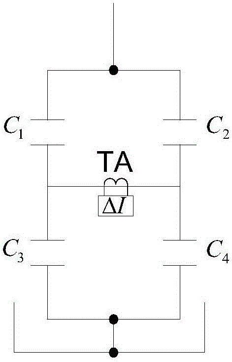
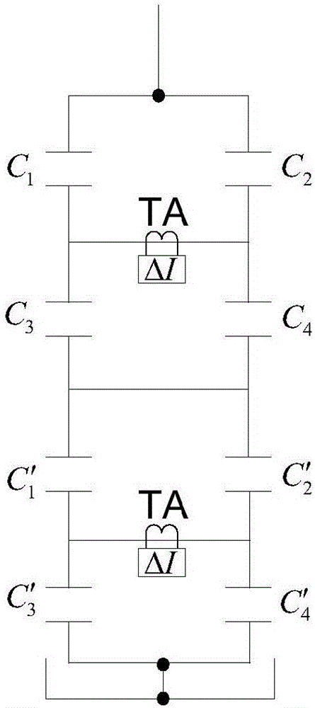
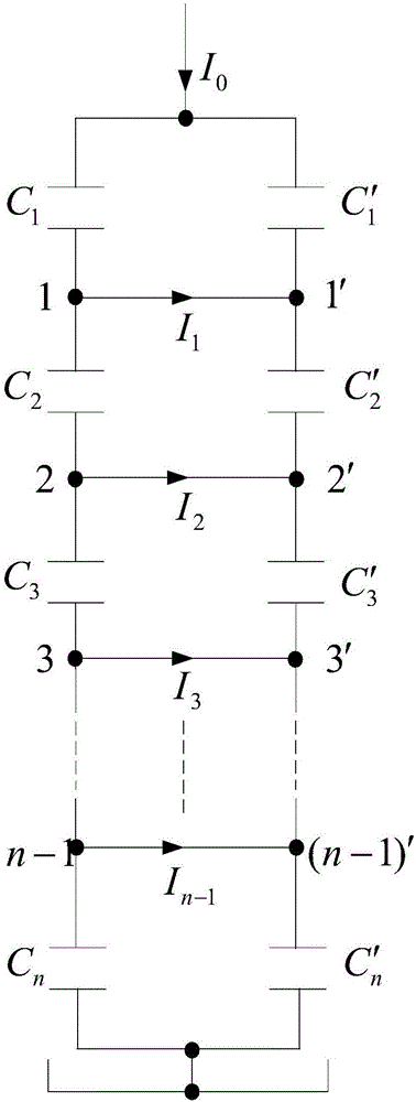
[0037] Such as image 3 As shown, the main wiring structure in a capacitor bank of the present invention divides the capacitor bank into two strings with the same number of series, and connects some or all of the equipotential points in the two strings, and connects at least two places, Each connection line is connected with a current transformer, and the current change measured by the current transformer and the change of the bus current of the capacitor bank can be used to determine the scope of the fault and determine the fault point. where C 1 and C' 1 、C 2 and C' 2 、C 3 and C' 3 ...C n and C' n Refers to each pair of capacitor banks with the same number, connect each pair of capacitor banks to form a series of bridges, measure the magnitude and phase of the current on the ...


PUM


Abstract

The invention provides a capacitor bank main wiring structure and a fault judgment method. According to the capacitor bank main wiring structure, a capacitor bank is divided into two strings of capacitor banks with the same series number, part or all equipotential points in the two strings of capacitor banks are connected through connecting wires, at least two parts are connected, and each connecting wire is connected to a current transformer. The calculation is simple, only the phase of bus current, the size of the current of each connecting wire and the phase, which takes the phase of the bus current as a reference, of the current of each connecting wire are required to be measured, and if a capacitor fault occurs, the location of the fault can be judged through the size and the phase of the current of each connecting wire.

Description

【Technical field】 [0001] The invention relates to a power capacitor, in particular to a capacitor bank main wiring structure and a fault judgment method. 【Background technique】 [0002] With more and more ultra-high voltage and ultra-high voltage direct current transmission projects, power capacitors are used as reactive power compensation and harmonic filtering. Large size, many strings, and many capacitors. [0003] Currently, if figure 1 As shown, the commonly used capacitor bank adopts the bridge differential protection method, including capacitors C1, C2, C3, C4 and current transformer TA. It can only detect capacitor failures and the sensitivity is not high, but the location of the fault point cannot be determined. Such as figure 2 As shown, some companies have proposed a double-bridge differential unbalance protection method, including multiple capacitors C and two current transformers TA. This protection method improves the protection sensitivity, but it is diffi...

Claims


Application Information

Patent Timeline
Patent Type & Authority Applications(China)
IPC IPC(8): G01R31/08H02H7/16
CPCG01R31/086H02H7/16
Inventor 姚成尤鸿芃林丽妲
Owner CHINA XD ELECTRIC CO LTD
Features
  • R&D
  • Intellectual Property
  • Life Sciences
  • Materials
  • Tech Scout
  • Unparalleled Data Quality
  • Higher Quality Content
  • 60% Fewer Hallucinations
Learn More