Adjustment and Calibration Mechanism for Thermal Overload Relay

A technology of thermal overload relay and calibration mechanism, which is applied in the direction of calibration/finding protection devices, circuits, electrical components, etc., can solve the problems of unsuitable calibration of thermal overload relay products, prone to internal stress changes, difficult adjustment operations, etc., to achieve improvement Large-scale adjustment function, improved calibration accuracy and convenience, and improved production efficiency

Active Publication Date: 2019-01-04
ZHEJIANG CHINT ELECTRIC CO LTD
View PDF7 Cites 0 Cited by
  • Summary
  • Abstract
  • Description
  • Claims
  • Application Information

AI Technical Summary

Problems solved by technology

Although this structure is also used to adjust the error between the setting value and its corresponding actual current, the adjustment accuracy of this method is low, and internal stress changes are prone to occur, so the adjustment operation is difficult, and when the accuracy requirements cannot be met, it needs to be repeated. Operation, which leads to the problems of long time consumption and low production efficiency, and is not suitable for the calibration of large-scale production of thermal overload relay products

Method used


Image

  • Adjustment and Calibration Mechanism for Thermal Overload Relay
  • Adjustment and Calibration Mechanism for Thermal Overload Relay
  • Adjustment and Calibration Mechanism for Thermal Overload Relay

Examples


Embodiment Construction

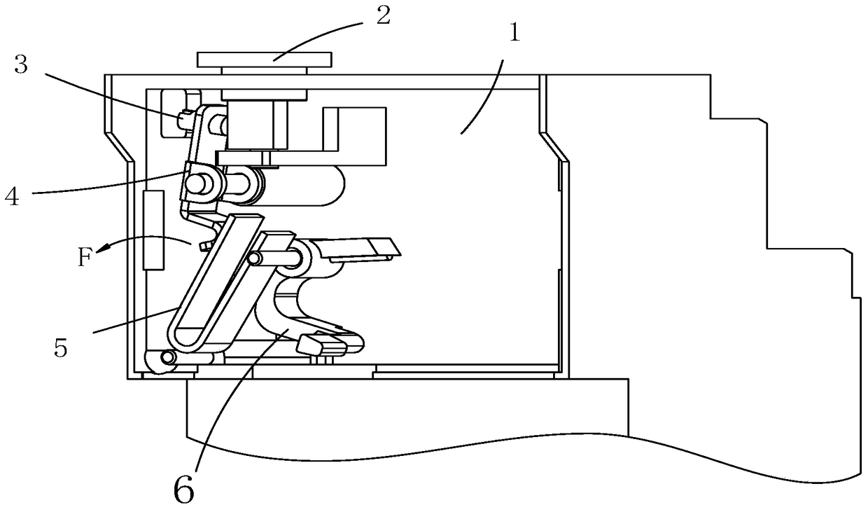
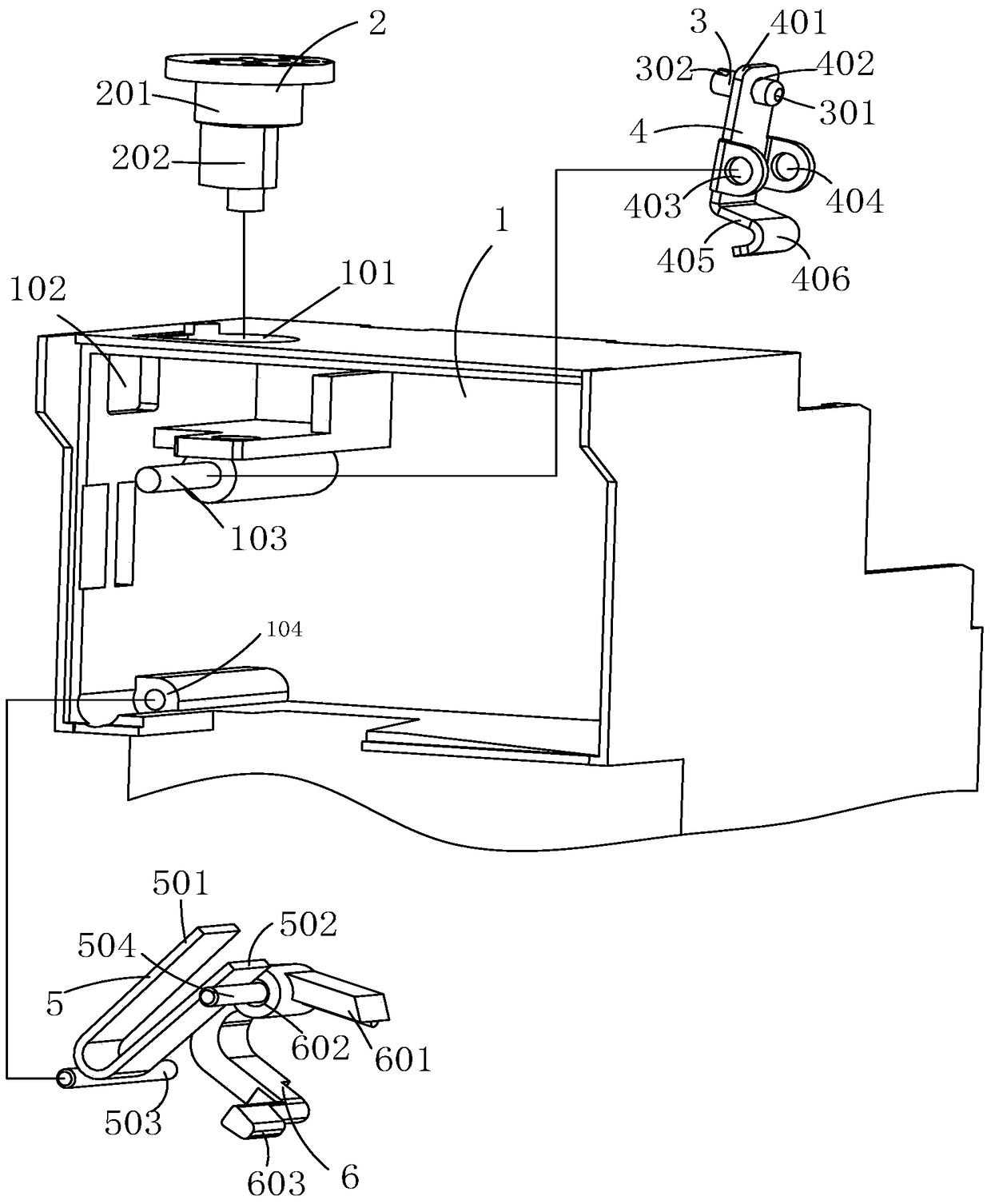
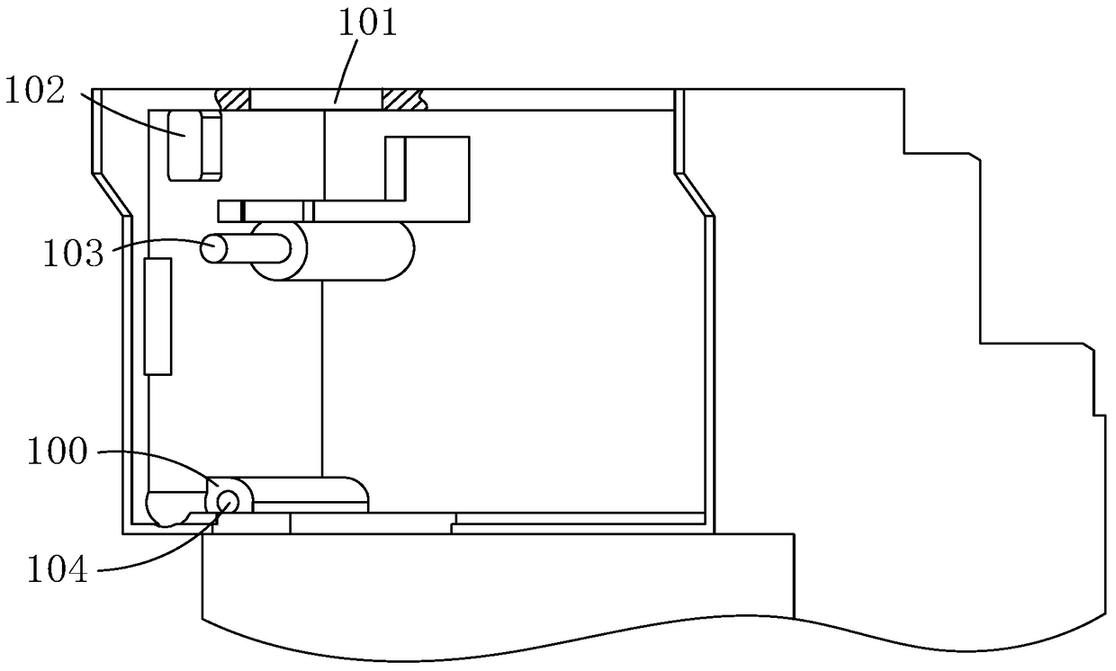
[0026] The following is attached Figures 1 to 8 The given examples further illustrate the specific implementation of the adjustment and calibration mechanism of the thermal overload relay of the present invention.

[0027] exist figure 1 In the given embodiment, the adjustment and calibration mechanism of the thermal overload relay of the present invention includes a trip lever 6 installed in the housing 1, and the trip lever 6 is connected with the contact opening and closing mechanism of the relay and the main bimetal The lever coupling of the main bimetal can drive the tripping lever 6 to trigger the tripping of the contact opening and closing mechanism. By adjusting the position of the tripping lever 6 and changing the contact distance of the coupling, the contact opening and closing mechanism of the relay can be changed. Thermal tripping performance between bimetals. see figure 2 As shown, the adjustment and calibration mechanism also includes an adjustment driving d...


PUM


Abstract

The invention relates to an adjustment and calibration mechanism of a thermal overload relay. The adjustment and calibration mechanism comprises a tripping lever mounted in a housing, wherein the tripping lever can be coupled to the contact disengagement and engagement mechanism and main bimetal of the relay, wherein the main bimetal can drive the tripping lever to trigger the contact disengagement and engagement mechanism to trip; the adjustment and calibration mechanism further comprises an adjustment driving device mounted on the housing, a lever pivotally mounted on the housing and a temperature compensation bimetal pivotally mounted on the housing; the tripping lever is pivotally mounted on the temperature compensation bimetal; the adjustment driving device is connected with one end of the lever so as to make the lever rotate; the lever is matched with the temperature compensation bimetal; and the lever can be made to rotate through the adjustment driving device so as to drive the temperature compensation bimetal to rotate, so that the position of the tripping lever arranged on the temperature compensation bimetal can be changed, and therefore, the bending amount of the bimetal of the main circuit of the thermal overload relay can be transferred to the contact disengagement and engagement mechanism of the relay, so that the thermal overload relay can act more accurately and finely.

Description

technical field [0001] The invention belongs to the field of relays, in particular to a thermal overload relay, in particular to an adjustment and calibration mechanism for a thermal overload relay. Background technique [0002] The thermal overload relay is a commonly used relay. In use, the bimetal is connected in series in the main circuit controlled by the thermal overload relay. When the current flowing through the main circuit of the bimetal is less than or equal to the rated current, the bimetal is activated. Heating to a certain bending stroke, but not enough to push the reset action mechanism of the thermal overload relay to operate to ensure the normal start and operation of the load (such as a motor); when there is an overload current (greater than the rated current) or an abnormal phase failure in the main circuit, The bimetal is heated to a larger bending stroke and is enough to push the action mechanism of the thermal overload relay to produce a tripping action...

Claims


Application Information

Patent Timeline
Patent Type & Authority Patents(China)
IPC IPC(8): H01H69/01
CPCH01H69/01H01H2069/013
Inventor 林铸鑫胡建国陈琼叶扬
Owner ZHEJIANG CHINT ELECTRIC CO LTD
Why Eureka
Try Eureka