A magnetron anode assembly and a magnetron provided with the magnetron anode assembly

An anode assembly and magnetron technology, applied in the field of magnetron, can solve the problems of easy deformation of welding ring, scrapped workpiece, short circuit, etc., and achieve the effects of high welding quality, avoiding welding failure and stable working frequency

Active Publication Date: 2019-06-28
GUANGDONG WITOL VACUUM ELECTRONICS MFR
View PDF6 Cites 1 Cited by
  • Summary
  • Abstract
  • Description
  • Claims
  • Application Information

AI Technical Summary

Problems solved by technology

However, during the installation of the solder 14, the welding ring is easily deformed, causing its diameter to be less than the inner diameter of the anode cylinder 11 (such as Image 6 As shown), that is, the solder 14 cannot be close to the inner wall of the anode cylinder 11. When the solder 14 melts, the solder 14 is directly melted on the upper end of the anode vane 12 (such as Figure 7 As shown), it is difficult to flow into the connection between the anode blade 12 and the anode cylinder 11, so that the welding of the anode blade 12 and the anode cylinder 11 fails, and the operating frequency of the magnetron deviates from the design value
What is more serious is that when the solder 14 accumulates at the upper end of the anode vane 12, it may flow to the suspension between the anode vane 12 and the cross-connecting ring, so that the place where the anode vane 12 and the cross-connecting ring should be disconnected is short-circuited, causing the workpiece to be scrapped (such as Figure 8 shown)

Method used


Image

  • A magnetron anode assembly and a magnetron provided with the magnetron anode assembly
  • A magnetron anode assembly and a magnetron provided with the magnetron anode assembly
  • A magnetron anode assembly and a magnetron provided with the magnetron anode assembly

Examples


Embodiment 1

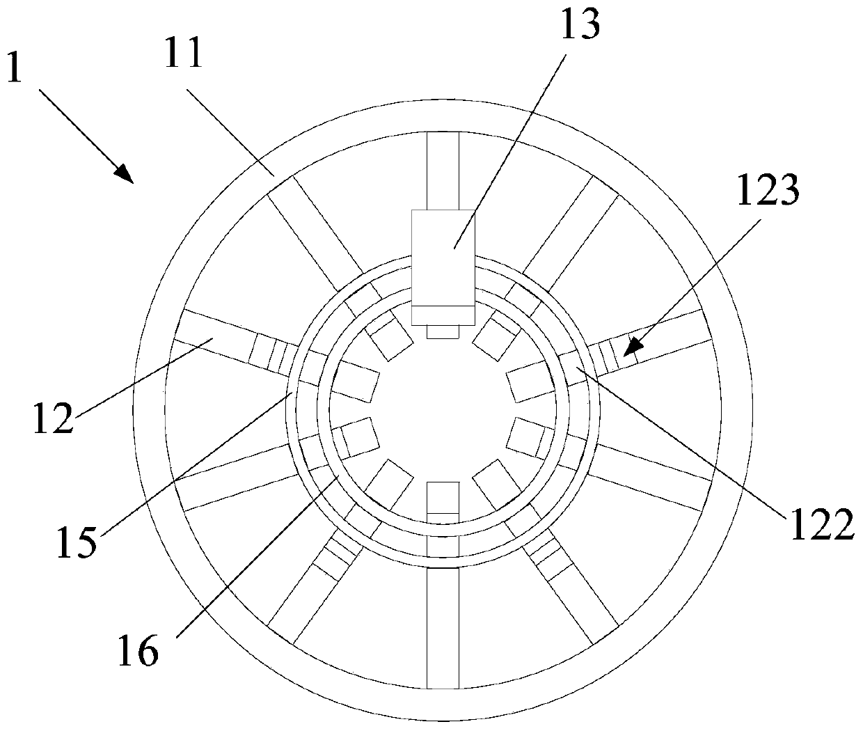
[0043] Such as Figure 10 to Figure 12 As shown, the present invention provides a magnetron anode assembly 1, comprising an anode cylinder 11 and a plurality of radially distributed anode blades 12 arranged in the anode cylinder 11, and a plurality of anode blades 12 One end is respectively connected with the inner wall of the anode cylinder 11, and the other end is a free end, and the joint between each anode vane 12 and the inner wall of the anode cylinder 11 is welded by solder 14; Two diversion grooves 121, two diversion grooves 121 are arranged on the side wall of one side of the diversion groove 121, and the diversion groove 121 includes a first diversion section 1211 arranged horizontally and a second diversion section 1212 arranged obliquely One end of one of the guide grooves 121 extends to the upper surface of the anode blade 12, and the other end extends to the end where the anode blade 12 and the inner wall of the anode cylinder 11 are welded; one end of the other ...

Embodiment 2

[0056] This embodiment is substantially the same as the technical solution in Embodiment 1, the main difference is that two diversion grooves 121 are provided on the side wall of the diversion groove 121 in this embodiment, as Figure 13 and Figure 14 As shown, the guide groove 121 includes a first guide section 1211 arranged horizontally and a second guide section 1212 arranged obliquely, and the length d1 of the second guide section 1212 from the welding end of the anode blade 12 and the anode cylinder 11 is 0- 4mm, and the angle between the second guide section 1212 and the upper surface of the anode vane 12 is 30-90°, because the welding ring used for welding the anode vane 12 is generally placed between the anode vane 12 and the anode cylinder 11 At the gap, if the distance is too large, the solder 14 melted on the upper surface of the anode vane 12 is too far away from the diversion groove 121, and the solder 14 cannot be guided to the welding place between the anode va...

Embodiment 3

[0061] The technical solution of this embodiment is substantially the same as that of Embodiment 1, the main difference is that in this embodiment, only one diversion groove 121 is provided on the same side of the anode vane 12, such as Figure 15 As shown, a diversion groove 121 is provided on the side wall of one side of the diversion groove 121, and one end of the diversion groove 121 extends to the upper surface of the anode vane 12, and the other end extends to the welded joint between the anode vane 12 and the inner wall of the anode cylinder 11. one end. In this way, when the anode vane 12 and the anode cylinder 11 are welded, the solder 14 is melted on the upper surface of the anode vane 12, and then the melted solder 14 flows to the anode vane 12 and the anode vane 12 through the guide groove 121 under the action of capillary action and gravity. At the welding place of the inner wall of the anode cylinder 11 , the anode blades 12 are welded on the inner wall of the an...


PUM


Abstract

The invention relates to the technical field of magnetrons, in particular to a magnetron anode assembly and a magnetron provided with the magnetron anode assembly. The magnetron anode vane assembly provided by the present invention includes an anode cylinder and a plurality of anode vanes arranged in the anode cylinder, each anode vane is provided with at least one diversion groove, wherein at least one diversion groove is used to place the The melted solder on the upper surface of the vane is guided to the end where the anode vane is welded to the inner wall of the anode cylinder, so that when the anode vane and the anode cylinder are welded, the solder melts on the upper surface of the anode vane, and then passes through the capillary action and gravity of the melted solder Under the action of the guide groove, it flows to the welding place between the anode blade and the inner wall of the anode cylinder, avoiding the problem of welding failure between the anode blade and the anode cylinder caused by the accumulation of solder on the upper surface of the anode blade, and making the working frequency of the magnetron more stable. The welding quality of the anode vane and the anode cylinder is higher, the success rate of welding is improved, and the manufacturing cost is reduced.

Description

technical field [0001] The invention relates to the technical field of magnetrons, in particular to a magnetron anode assembly and a magnetron provided with the magnetron anode assembly. Background technique [0002] Magnetron is a vacuum electron tube that generates microwaves. Because of its high oscillation efficiency and high microwave output power, it is widely used as a microwave source for microwave applications such as household microwave ovens and industrial microwave heating equipment. Such as figure 1 As shown, the existing magnetron includes a shell 3, a tube core (not labeled in the figure) located in the shell 3, an input power supply 4 located at the bottom of the shell 3, and an input power supply 4 located between the inner wall of the shell 3 and the outer wall of the tube core. Between the cooling parts 5, where such as figure 2 As shown, the tube core includes an anode part, a cathode part 2, an output part 6 and a magnetic pole part forming a magnetic...

Claims


Application Information

Patent Timeline
Patent Type & Authority Patents(China)
IPC IPC(8): H01J23/027H01J25/50
CPCH01J23/0275H01J25/50
Inventor 刘志勇
Owner GUANGDONG WITOL VACUUM ELECTRONICS MFR
Why Eureka
Try Eureka