Low-voltage capacitor element replacing device for 500kV transformer station

A low-voltage capacitor and substation technology, applied in the field of low-voltage capacitor element replacement devices for 500kV substations, can solve problems such as complex structure and cumbersome operation process, and achieve the effects of improving safety, saving labor load, and improving work efficiency

Active Publication Date: 2017-05-24
国网河南省电力公司超高压公司 +1
View PDF10 Cites 2 Cited by
  • Summary
  • Abstract
  • Description
  • Claims
  • Application Information

AI Technical Summary

Problems solved by technology

Although this structure is convenient for single-person operation, its complex structure causes more tedious work in the operation process.

Method used


Image

  • Low-voltage capacitor element replacing device for 500kV transformer station
  • Low-voltage capacitor element replacing device for 500kV transformer station
  • Low-voltage capacitor element replacing device for 500kV transformer station

Examples


Embodiment 1

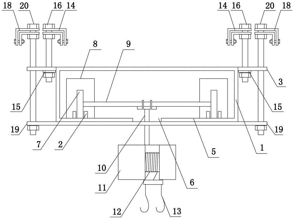
[0039] Such as Figure 2 to Figure 6 Shown, the present invention comprises walking mechanism and supporting hanging mechanism:

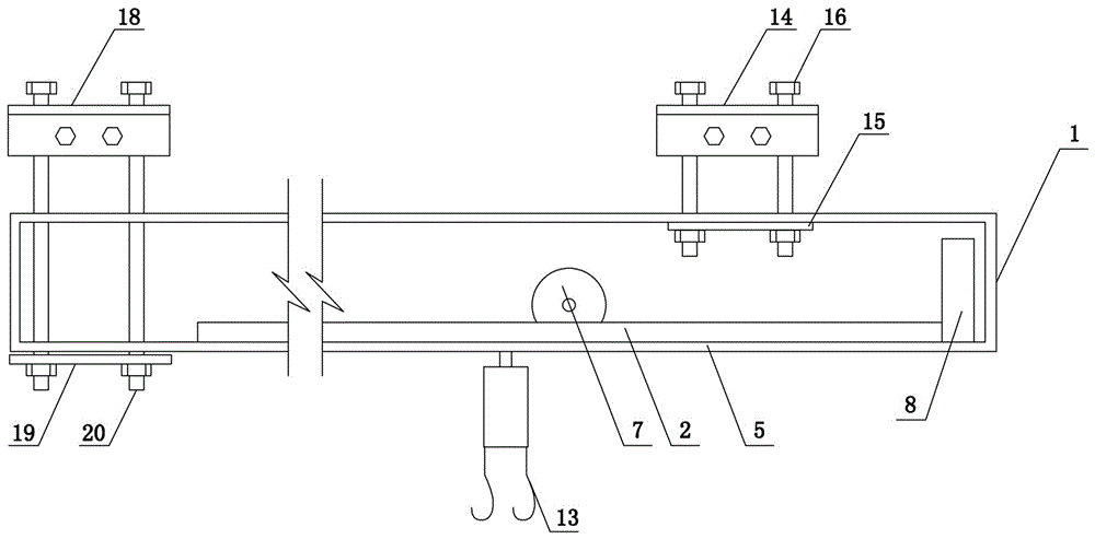
[0040] The traveling mechanism comprises a rectangular parallelepiped frame 1 and guide rails 2. Extension plates 3 are arranged on both sides of the upper end of the rectangular parallelepiped frame 1. The extension plate 3 is provided with a through hole 4. There are multiple through holes 4. The lower end of the rectangular parallelepiped frame 1 is welded with a bottom plate 5. The strip hole 6 and the guide rail 2 are fixedly welded on the upper end surface of the bottom plate 5. The two guide rails 2 are respectively located on both sides of the strip hole 6. Rollers 7 are installed on the two guide rails 2, and the front ends of the two guide rails 2 are both limited. The position block 8 and the limit block 8 are made of rubber. A support rod 9 is installed between the two rollers 7. A suspender 10 is arranged on the support pole 9. The lowe...

Embodiment 2

[0043] The traveling mechanism comprises a rectangular parallelepiped frame 1 and guide rails 2. Extension plates 3 are arranged on both sides of the upper end of the rectangular parallelepiped frame 1. The extension plate 3 is provided with a through hole 4. There are multiple through holes 4. The lower end of the rectangular parallelepiped frame 1 is welded with a bottom plate 5. The strip hole 6 and the guide rail 2 are fixedly welded on the upper end surface of the bottom plate 5. There are two guide rails 2, which are respectively located on both sides of the elongated hole 6. Rollers 7 are installed on the two guide rails 2, and the rollers 7 have a built-in drive motor 21. The driving motor 21 is a permanent magnet motor. The power supply 22 and the control switch 23 are installed on the rectangular parallelepiped frame 1. The power supply 22 can use a 36V rechargeable lithium battery. The control switch 23 is a forward and reverse switch. 8. The limit block 8 is made of...

Embodiment 3

[0047] The structure of this embodiment is basically the same as that of Embodiment 1, the difference is: as Figure 9 As shown, the through hole 4 on the extension plate 3 is a long strip structure, and the extension direction of the through hole 4 is perpendicular to the extension direction of the guide rail 2. This structure design can make the electric hoist 11 install electric power by fine-tuning the cuboid frame 1 left and right during installation. Directly above the capacitor, that is, the cuboid frame 1 is preliminarily fixed through the front threaded suspender 16 and the rear threaded suspender 20 during the use process, and then the position of the electric hoist 11 and the position of the power capacitor are combined to fine-tune the cuboid frame 1 left and right. The calibration of the cuboid frame 1 is realized without dismantling multiple front threaded suspenders 16 and rear threaded suspenders 20, effectively improving the operating efficiency of the installa...


PUM


Abstract

The invention discloses a low-voltage capacitor element replacing device for a 500kV transformer station, and the device comprises a traveling mechanism and a suspension mechanism. The traveling mechanism comprises a cuboid frame and a guide rail, and the guide rail is provided with an electric block. The suspension mechanism comprises front suspension assemblies and rear suspension assemblies, wherein the front and rear suspension assemblies are located at two ends of the traveling mechanism. There are two groups of front suspension assemblies, and each group of front suspension assemblies comprise a front upper clamping part, a front lower clamping part, and a front threaded suspension rod, wherein the front threaded suspension rod enables the upper end of the cuboid frame to be fixed with a capacitor platform frame. There are two groups of rear suspension assemblies, and each group of rear suspension assemblies comprise a rear upper clamping part, a rear lower clamping part, and a rear threaded suspension rod, wherein the rear threaded suspension rod enables the lower end of the cuboid frame to be fixed with the capacitor platform frame, and the front end of the cuboid frame stretches out of the capacitor platform frame. The device is provided with the traveling mechanism and the suspension mechanism, effectively simplifies the operation process, and reduces the workload. Moreover, an extending board is provided with through holes in different shapes, thereby achieving the suspension of the device exactly above a capacitor, and facilitating the quick operation.

Description

technical field [0001] The invention belongs to the technical field of substation equipment maintenance, and in particular relates to a device for replacing low-voltage capacitor elements in a 500kV substation. Background technique [0002] Power capacitors are energy storage appliances widely used in electrical systems, which play an important role in the safe and stable operation of power transmission and transformation systems. Under normal circumstances, power capacitors are installed in the substation in the form of a complete set of power capacitors, and run together with other equipment in the substation. The height of the 35kv and 66kv capacitor banks in the 500kv substation is more than 6 meters. Due to the restrictions and costs of the substation site Restricted by factors such as control, the power capacitor is vertical (such as figure 1 shown) or horizontally fixed on the capacitor platform frame composed of I-beam or angle steel. In order to prevent the power c...

Claims


Application Information

Patent Timeline
Patent Type & Authority Applications(China)
IPC IPC(8): H02B3/00
CPCH02B3/00
Inventor 李璐曲欣王兴友王毅吴西博娄遂山胡润阁牛田野鲁永王校丹李皓张晓衡李洪波张建国苗亚楠张文明
Owner 国网河南省电力公司超高压公司
Why Eureka
Try Eureka