Terminal locating method and device
A positioning method and terminal technology, applied in the field of communications, can solve problems such as low positioning accuracy
- Summary
- Abstract
- Description
- Claims
- Application Information
AI Technical Summary
Problems solved by technology
Method used
Image

Examples
Embodiment 1
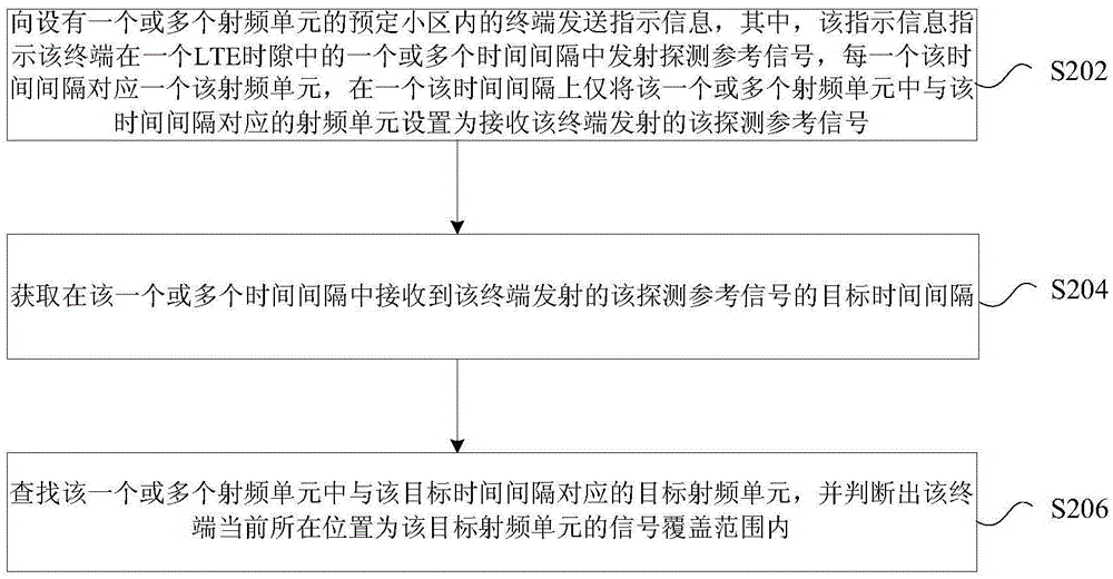
[0031] In this embodiment, a terminal positioning method is provided, figure 2 is a flowchart of a positioning method for a terminal according to an embodiment of the present invention, such as figure 2 As shown, the process includes the following steps:
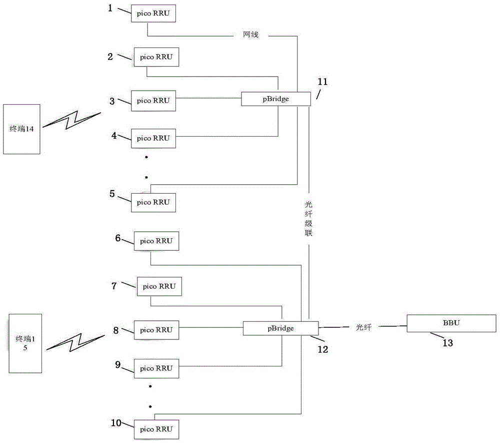
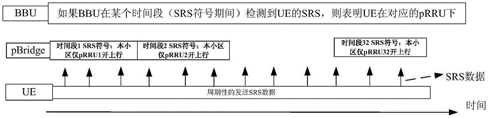
[0032] Step S202, sending instruction information to a terminal in a predetermined cell with one or more radio frequency units, wherein the instruction information instructs the terminal to transmit sounding reference signals in one or more time intervals in one LTE time slot, every One time interval corresponds to one radio frequency unit, and in one time interval, only the radio frequency unit corresponding to the time interval among the one or more radio frequency units is set to receive the sounding reference signal transmitted by the terminal;
[0033] Step S204, acquiring a target time interval at which the sounding reference signal transmitted by the terminal is received in the one or more time intervals;
[0034]...
Embodiment 2
[0085] In this embodiment, a device for locating a terminal is also provided, and the device is used to implement the above embodiments and preferred implementation manners, and those that have already been described will not be repeated. As used below, the term "module" may be a combination of software and / or hardware that realizes a predetermined function. Although the devices described in the following embodiments are preferably implemented in software, implementations in hardware, or a combination of software and hardware are also possible and contemplated.
[0086] Figure 5 is a structural block diagram of a terminal positioning device according to an embodiment of the present invention, such as Figure 5 As shown, the device includes the following modules:
[0087] 1) The first sending module 52 is configured to send indication information to a terminal in a predetermined cell provided with one or more radio frequency units, wherein the indication information indicate...
Embodiment 3
[0117] The embodiment of the invention also provides a storage medium. For the application scenarios and examples of this embodiment, reference may be made to Embodiment 1 and Embodiment 2, and details are not described here. Optionally, in this embodiment, the above-mentioned storage medium may be configured to store program codes for performing the following steps:
[0118] S1. Send indication information to a terminal in a predetermined cell with one or more radio frequency units, where the indication information instructs the terminal to transmit sounding reference signals in one or more time intervals in one LTE time slot, each The time interval corresponds to one radio frequency unit, and in one time interval, only the radio frequency unit corresponding to the time interval among the one or more radio frequency units is set to receive the sounding reference signal transmitted by the terminal;
[0119] S2. Obtain a target time interval at which the sounding reference sig...
PUM
 Abstract
Description
Claims
Application Information
 - R&D
- Intellectual Property
- Life Sciences
- Materials
- Tech Scout
- Unparalleled Data Quality
- Higher Quality Content
- 60% Fewer Hallucinations
Browse by: Latest US Patents, China's latest patents, Technical Efficacy Thesaurus, Application Domain, Technology Topic, Popular Technical Reports.
© 2025 PatSnap. All rights reserved.Legal|Privacy policy|Modern Slavery Act Transparency Statement|Sitemap|About US| Contact US: help@patsnap.com