Supercharge Your Innovation With Domain-Expert AI Agents!

Illumination optical unit for a projection exposure system

A technology of optical unit and exposure system, applied in optics, microlithography exposure equipment, photoplate making process of pattern surface, etc., can solve the problem of radiation loss polarization effect, etc., and achieve the effect of reducing radiation loss and improving optical properties

Active Publication Date: 2017-05-24
CARL ZEISS SMT GMBH
View PDF5 Cites 2 Cited by
  • Summary
  • Abstract
  • Description
  • Claims
  • Application Information

AI Technical Summary

Problems solved by technology

This can lead to undesired radiation losses and / or undesired polarization effects

Method used


Image

  • Illumination optical unit for a projection exposure system
  • Illumination optical unit for a projection exposure system
  • Illumination optical unit for a projection exposure system

Examples


Embodiment Construction

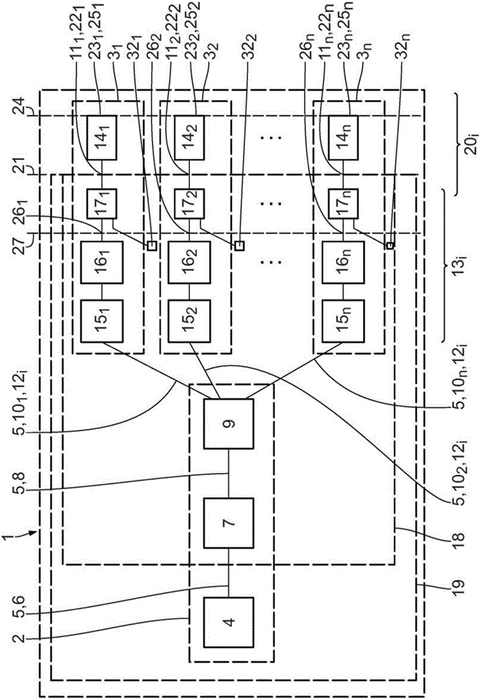
[0056] Preliminary reference below figure 1 The basic components of the projection exposure system 1 will be described.

[0057] The subdivision of the projection exposure system 1 into subsystems is used below mainly to differentiate their nomenclature. These subsystems can form separate structured subsystems. However, the distinction into subsystems is not necessarily reflected in the structural division.

[0058] The projection exposure system 1 comprises a radiation source module 2 and a plurality of scanners 3 i .

[0059] The radiation source module 2 contains a radiation source 4 for generating illumination radiation 5 .

[0060] The radiation source 4 is in particular a free electron laser (FEL). The radiation source may also be a synchrotron radiation source or a synchrotron radiation-based radiation source, which produces coherent radiation with a very high luminance. For such radiation sources, reference is made by way of example to US 2007 / 0152171 A1 and DE 1...


PUM

PropertyMeasurementUnit
angleaaaaaaaaaa

Abstract

An illumination optical unit (17i) for a projection exposure system (1) comprises a plurality of radiation-reflecting components, wherein all of the radiation-reflecting components are arranged in such a way that a beam (10i) with illumination radiation (5) is deflected at these in the same sense.

Description

[0001] Cross References to Related Applications [0002] This application claims priority from German patent application DE 10 2014 221 175.1, the content of which is hereby incorporated by reference. technical field [0003] The invention relates to an illumination optics unit of a projection exposure system, in particular to an illumination optics unit of a projection exposure system in which a free electron laser (FEL) acts as a radiation source. The invention further relates to an illumination system comprising at least one such illumination optics unit, an optical system comprising an illumination optics unit and a projection optics unit, and a projection exposure system comprising at least one such illumination optics unit. Finally the invention relates to a method of manufacturing microstructured or nanostructured components, and components produced according to this method. Background technique [0004] In projection exposure equipment, the illuminating radiation em...

Claims


Application Information

Patent Timeline
Patent Type & Authority Applications(China)
IPC IPC(8): G03F7/20
CPCG03F7/70075G03F7/70116G03F7/702G03F7/70208G03F7/70991
Inventor M.帕特拉S.比林M.德冈瑟R.米勒
Owner CARL ZEISS SMT GMBH
Features
  • R&D
  • Intellectual Property
  • Life Sciences
  • Materials
  • Tech Scout
  • Unparalleled Data Quality
  • Higher Quality Content
  • 60% Fewer Hallucinations
Learn More