Balloon following device for stents

A support device and balloon technology, applied in the field of medical vascular interventional therapy, can solve problems such as blood vessel rupture, disease deterioration, death, etc., and achieve the effects of prolonging service life, reducing patient pain, and convenient operation

Inactive Publication Date: 2017-05-31
重庆康华众联心血管病医院有限公司
View PDF7 Cites 2 Cited by
  • Summary
  • Abstract
  • Description
  • Claims
  • Application Information

AI Technical Summary

Problems solved by technology

In the actual operation process, the phenomenon of stent stringing is easy to occur when the stent is positioned, especially for open lesions that require precise positioning, which causes the following risks in the existing vascular stent delivery device: insufficient coverage of lesions; poor stent apposition, increased In-stent thrombosis or risk of restenosis; over-expansion of the stent-loaded balloon in the stent can cause damage to small distal blood vessels, bulge on the edge of the stent, and risk of vessel rupture; repeated long-term positioning can lead to prolonged myocardial ischemia time, May lead to worsening of condition and even death

Method used


Image

  • Balloon following device for stents
  • Balloon following device for stents

Examples


Embodiment 1

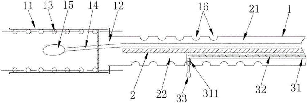
[0024] Such as figure 1 As shown, if the blood-blocking target blood vessel is small, it is not suitable to use the blood-blocking air bag 15, then directly use the hemostat to clamp the target blood vessel; then select the opening compression spring 13 that is compatible with the inner diameter of the supporting target blood vessel, and place the opening compression spring 13 Put it into the sleeve 11 after extrusion, make the extension end of the opening compression spring 13 abut on the baffle 12, the air guide tube 14 passes through the baffle 12, and communicates with the support air bag 15, at the same time, let the catheter body 1 The support airbag 15 on the upper end is set in the opening compression spring 13, and extends into the blood vessel along the catheter body 1 until the sleeve 11 reaches the position of supporting the target blood vessel. At this time, the support airbag 15 is inflated, and the outer surface of the support airbag 15 touches the The inner sid...

Embodiment 2

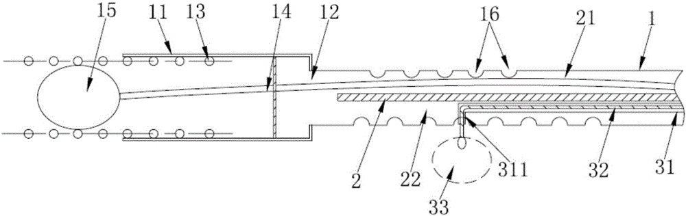
[0026] Such as figure 2 As shown, if the target blood vessel is large, in order to avoid damage to the blood vessel by the hemostat, it is suitable to use the hemostatic airbag 15 at this time. Turn the eight through holes on the second cavity 22 separated by the spacer 2 to the direction of the target blood vessel for blocking blood. Referring to the display of the auxiliary equipment, insert the guide tube 31 into the through hole at the corresponding position, and make the bending Segment 311 is aligned with the corresponding through hole, and then, it is introduced into the inflatable tube 32, and the extending end of the inflatable tube 32 is also connected with a blocking air bag 33, and the inflatable tube 32 is inserted into the target blood vessel to block blood under the guidance of the guide tube 31, and then , inflate the inflation tube 32, block the inflation of the air bag 33 ( figure 2 middle dotted line), block the blood vessel to achieve the purpose of bloc...


PUM


Abstract

The invention discloses a balloon following device for stents. The balloon following device comprises a catheter (1). A support device is arranged at an end of the catheter (1), a support balloon (15) is further arranged in the support device and can be movably butted to the support device, and corresponding components of the support device can cling into the inner walls of blood vessels, so that the stabilization purpose can be achieved. The balloon following device has the advantages that the balloon following device is simple in structure; an open compression spring can be conveyed and released and can effectively cling to the inner walls of the blood vessels, accordingly, the balloon following device is favorable for supporting the inner-diameter sides of the target blood vessels and can be operated conveniently and quickly, the service life can be prolonged, suffering can be relieved for patients, and the cost can be reduced.

Description

technical field [0001] The invention relates to the technical field of medical vascular interventional therapy, in particular to a stent-balloon accompanying device. Background technique [0002] At present, the stent delivery device for clinical vascular interventional therapy is equipped with a balloon matching the diameter and length of the stent, which is used to expand, expand, shape and release the stent after reaching the vascular lesion site. In the actual operation process, the phenomenon of stent stringing is easy to occur when the stent is positioned, especially for open lesions that require precise positioning, which causes the following risks in the existing vascular stent delivery device: insufficient coverage of lesions; poor stent apposition, increased In-stent thrombosis or risk of restenosis; over-expansion of the stent-loaded balloon in the stent can cause damage to small distal blood vessels, bulge on the edge of the stent, and risk of vessel rupture; rep...

Claims


Application Information

Patent Timeline
Patent Type & Authority Applications(China)
IPC IPC(8): A61F2/958A61F2/962
CPCA61F2/958A61F2/962
Inventor 何云鲁雪梅耿召华宋明宝
Owner 重庆康华众联心血管病医院有限公司
Why Eureka
Try Eureka