Detection device for bearing base of thrust ball bearing

A technology of thrust ball bearings and testing equipment, which is applied to chemical instruments and methods, cleaning methods using liquids, cleaning methods and appliances, etc. It can solve the problems of insufficient system and comprehensive measurement items, inconvenient transportation and movement, and bulky equipment. Achieve the effect of simple structure, no need for manual operation, and high test accuracy

Inactive Publication Date: 2017-05-31
ZHEJIANG AET INTELLIGENT TECH
View PDF10 Cites 3 Cited by
  • Summary
  • Abstract
  • Description
  • Claims
  • Application Information

AI Technical Summary

Problems solved by technology

After the production of the thrust ball bearing housing is completed, detailed inspections such as washing and groove depth, inner diameter, and outer diameter are required. At present, there are more or less measurement items on the market that are not systematic enough, the measurement is not accurate enough, and manual work is required. Auxiliary operation, low measurement efficiency, too large equipment volume, inconvenient transportation and movement, etc., so it is necessary to improve and innovate the existing testing equipment for thrust ball bearing housings

Method used


Image

  • Detection device for bearing base of thrust ball bearing
  • Detection device for bearing base of thrust ball bearing
  • Detection device for bearing base of thrust ball bearing

Examples


Embodiment Construction

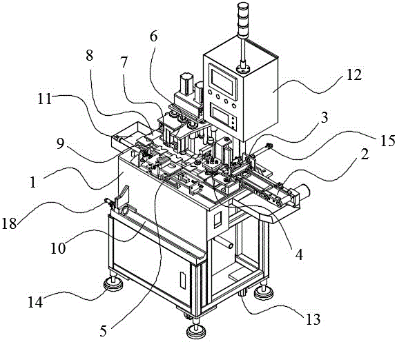
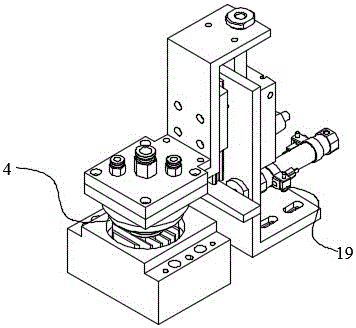
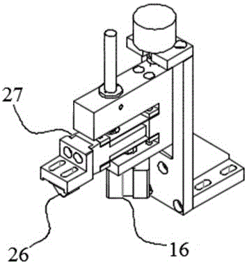
[0023] Below in conjunction with accompanying drawing and specific embodiment the present invention is described in further detail:

[0024] Thrust ball bearing housing testing equipment in this embodiment, such as figure 1 , figure 2 , image 3 , Figure 4 , Figure 5 , Figure 6 As shown, it includes: a frame 1, a conveyor belt 2, a push-pull rod 3 arranged at equal intervals on one side of the upper surface of the frame, a flushing nozzle 4, a groove depth measuring head 5, an inner diameter measuring head 6, and an outer diameter measuring head 7. Qualified product turning and unloading table 8, the bearing seat push-pull transmission plate 9 arranged on the other side of the upper surface of the frame 1 and the finished product groove 10 arranged on the side of the frame 1 outside the bearing seat push-pull transmission plate 9; push-pull rod 3. Flushing nozzle 4, groove depth measuring head 5, inner diameter measuring head 6, outer diameter measuring head 7, qualif...


PUM


Abstract

The invention relates to a detection device for a bearing base of a thrust ball bearing. The detection device comprises a machine frame, a conveyor belt, a push-pull rod, a washing spray head, a groove depth measuring head, an inner diameter measuring head, an outer diameter measuring head, a qualified product turnover discharging table, a bearing base push-pull transmission plate and a finished product groove, wherein the push-pull rod, the washing spray head, the groove depth measuring head, the inner diameter measuring head, the outer diameter measuring head, and the qualified product turnover discharging table are arranged on one side of the upper surface of the machine frame in sequence at equal intervals and sequentially correspond to stations 1-6, the bearing base push-pull transmission plate is arranged on the other side of the upper surface of the machine frame, the finished product groove is formed in the side surface, outside the bearing base push-pull transmission plate, of the machine frame, one end of the conveyor belt is fixed at a discharge port of the bearing base, the other end of the conveyor belt is fixed on the machine frame, and the finished product groove and the qualified product turnover discharging table are connected through a slide way in the machine frame. The detection device for the bearing base of the thrust ball bearing is compact in connection, free of manual operation, high in detection precision, high in speed, economical, practical, convenient and rapid, the design of each detection station is reasonable, and the economic benefits in the field of thrust ball bearing production are improved.

Description

technical field [0001] The invention relates to the technical field of bearing production equipment, in particular to a thrust ball bearing housing detection equipment. Background technique [0002] The thrust ball bearing housing is an important part of the thrust ball bearing and an indispensable part in the production process of the thrust ball bearing. After the production of the thrust ball bearing housing is completed, detailed inspections such as washing and groove depth, inner diameter, and outer diameter are required. At present, there are more or less measurement items on the market that are not systematic enough, the measurement is not accurate enough, and manual work is required. There are defects such as auxiliary operation, low measurement efficiency, too large equipment volume, and inconvenient transportation and movement. Therefore, it is necessary to improve and innovate the existing testing equipment for thrust ball bearing housings. Contents of the inven...

Claims


Application Information

Patent Timeline
Patent Type & Authority Applications(China)
IPC IPC(8): B07C5/06B08B3/02
CPCB07C5/065B08B3/02
Inventor 章干强李伟君许绪敏苏进浩
Owner ZHEJIANG AET INTELLIGENT TECH
Why Eureka
Try Eureka